- Three Parallel TCSPC / FLIM Channels + One Sync / Reference Channel or Four Parallel Absolute Timing Channels
- Time Channel Width Down to 4 ps
- IRF Width < 39 ps FWHM
- Typical Timing Jitter 16 ps RMS
- Excellent Timing Stability: Timing Drift over 10 Minutes <5 ps RMS
- Low Dead Time
- Adjustable SYNC Delay ± 128 ns
- High Peak Count Rate, up to 120 MHz
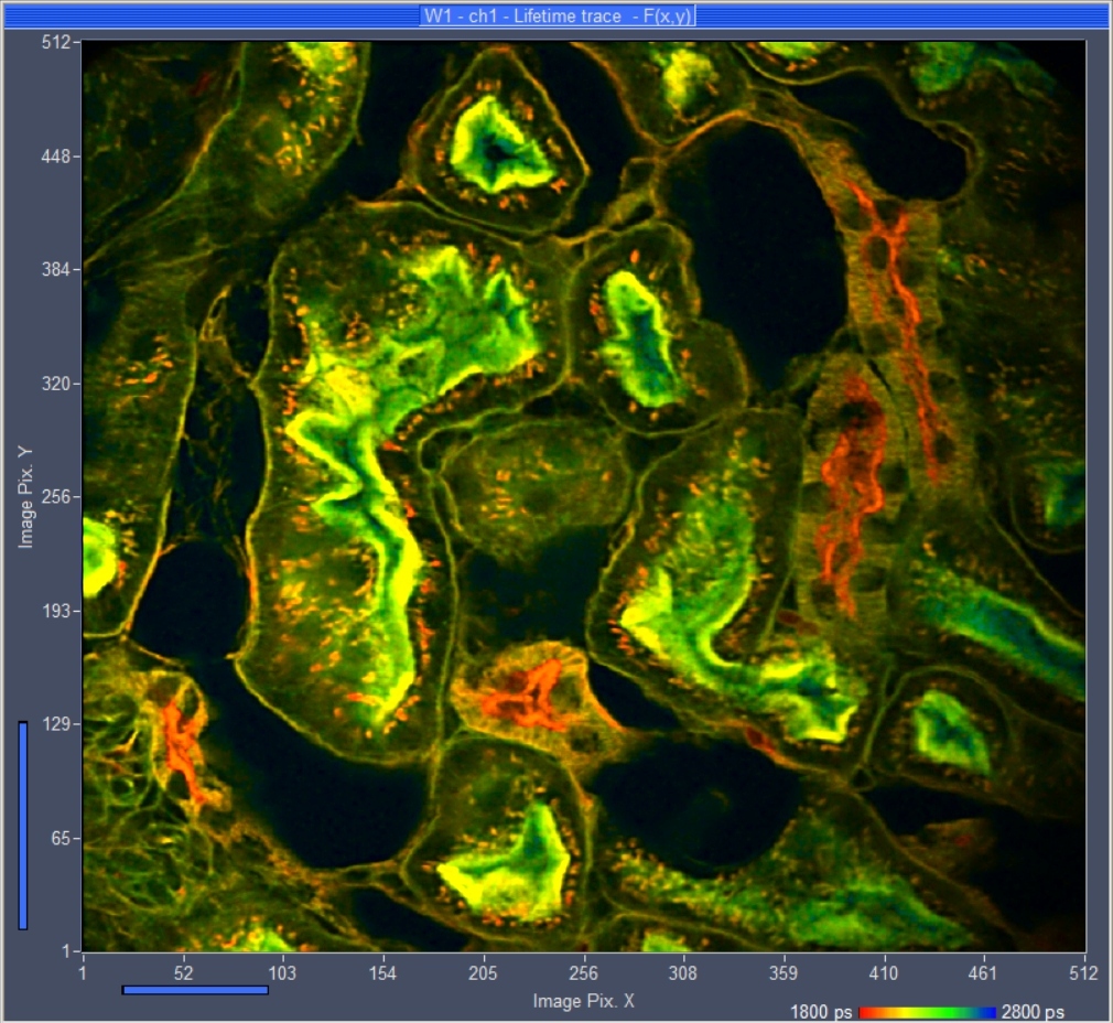
- Parallel FLIM in up to Three Detection Channels
- Fast-Acquisition FLIM
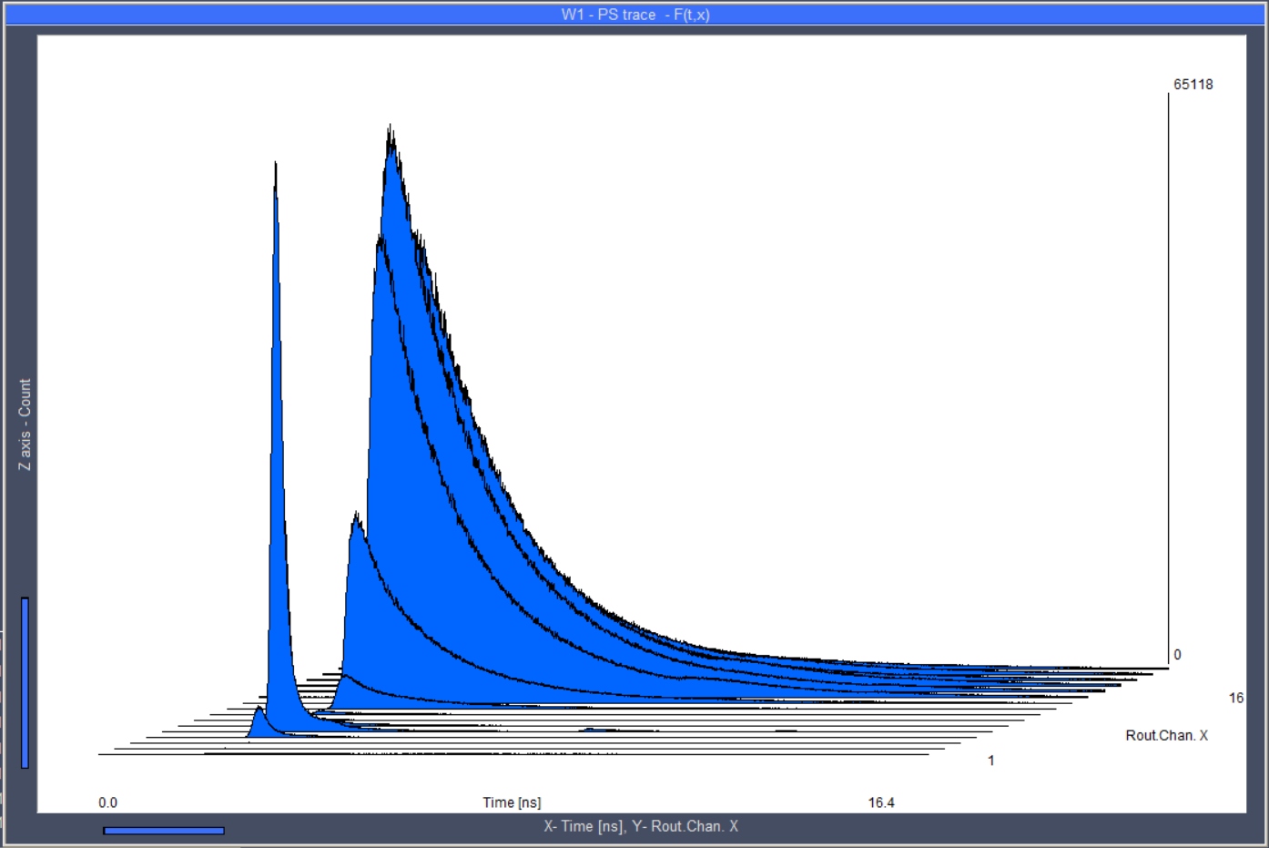
- Recording of Fluorescence Decay and Other Optical Waveforms
- Multi-Wavelength Detection of Fluorescence Decay and FLIM Data
- Photon Time- and Parameter Tagging
- Photon Correlation Down to the ps Range
- Free Instrument Software for Windows 10 / 11
Description
General Information
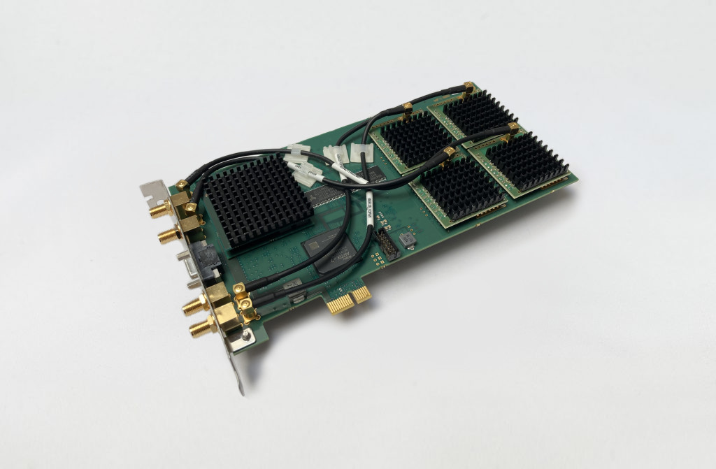
The SPC-QC-104 TCSPC / FLIM module has three parallel TCSPC / FLIM channels with a common reference channel on a single PCI-express board. Alternatively, the module can be operated with four absolute photon timing channels. The module features high temporal and spatial resolution, high peak count rate, and extraordinarily high timing stability. The SPC-QC-104 offers the usual modes for recording temporal waveforms of optical signals, sequential recording multi-wavelength recording, time- and parameter-tag recording, FLIM, spatial and temporal mosaic FLIM, triggered accumulation of fast time series of curves and images, and simultaneous FLIM / PLIM.
Measurement Software Included
The SPCM operating and measurement software is included with all SPC series modules. SPCM provides online calculation and display (2D, 3D) of data (decay curves, FCS, FCCS) acquired in multiple operation modes. SPCM software undergoes active continuous development. SPCM receives frequent updates with new features and bug fixes. Read more…
For fast online video FLIM streaming, please use ExpressFLIM as acquisition software.
FLIM and FCS Data Analysis
For advanced fluorescence lifetime imaging (FLIM) and single-curve data analysis, please use SPCImage.
For advanced visualisation and analysis of dynamic effects, please use SPCDynamics.
For advanced fluorescence correlation spectroscopy (FCS) and cross-correlation (FCCS) data analysis, please use Burst Analyzer.
Custom Programming Libraries (DLL, LabVIEW)
For automation and custom software integration, DLLs and LabVIEW drivers are available. Read more…
Specifications
|
Photon Channel |
|
|||
|
Principle |
Constant Fraction Discriminator (CFD) |
|||
|
Discriminator Input Bandwidth |
4 GHz |
|||
|
Optimum Input Voltage Range |
-30 mV to -500 mV |
|||
|
Min. Input Pulse Width |
200 ps |
|||
|
Threshold |
0 to -500 mV |
|||
|
Zero Cross Adjust |
-100 mV to 100 mV |
|||
|
Synchronisation Channel |
|
|||
|
Principle |
Constant Fraction Discriminator (CFD) |
|||
|
Discriminator Input Bandwidth |
4 GHz |
|||
|
Optimum Input Voltage Range |
-30 mV to -500 mV |
|||
|
Min. Input Pulse Width |
200 ps |
|||
|
Threshold |
0 to -500 mV |
|||
|
Zero Cross Adjust |
-100 mV to 100 mV |
|||
|
Frequency Range |
0 to 150 MHz |
|||
|
Frequency Divider |
1 – 2 - 4 |
|||
|
Adjustable Delay |
± 128 ns |
|||
|
Time-Measurement Circuitry |
|
|||
|
Principle |
Time-to-Digital Converter |
|||
|
IRF Width, FWHM |
< 39 ps |
|||
|
Typical RMS Timing Jitter |
16 ps |
|||
|
Time Range, at 4096 Time Channels |
16 ns to 68 µs |
|||
|
Min. Time / Channel |
4 ps |
|||
|
Timing Stability, Range 16 ns, over 10 min |
< 5 ps RMS |
|||
|
Diff. Nonlinearity |
< 1 % RMS |
|||
|
Dead Time |
8 ns |
|||
|
Histogram Modes |
||||
|
Method |
on-board multi-dim. histogramming process |
|||
|
Peak Count Rate, Each Channel |
120 MHz |
|||
|
Saturated Count Rate, Continuous |
40 MHz |
|||
|
Max. Counts / Time Channel (Counting Depth) |
216 - 1 |
|||
|
Max. No. Of Time Channels |
65,536 |
|||
|
Overflow Control |
none, stop, repeat and correct |
|||
|
Collection Time |
0.1 µs to 100,000 s |
|||
|
Display Interval Time |
10 ms to 100,000 s |
|||
|
Repeat Time |
0.1 µs to 100,000 s |
|||
|
Synchronisation with Scanning (Scan Sync IN Mode |
Pixel, line and frame clocks from scanning device |
|||
|
Routing |
4 bit, TTL |
|||
|
Count Enable |
1 bit, TTL |
|||
|
Experiment Trigger |
TTL |
|||
|
Data Acquisition |
FIFO / Parameter-Tag Mode |
|||
|
Method |
Parameter-tagging of individual photons, continuous writing to disk |
|||
|
Online Display |
Decay functions, FCS, Cross-FCS, PCH MCS Traces |
|||
|
FCS Calculation |
Multi-tau algorithm, online calculation and online fit |
|||
|
Number of Counts of Decay/ Waveform Recording |
Unlimited |
|||
|
Peak Count Rate |
120 MHz |
|||
|
Sustained Count Rate (Bus-Transfer Limit) |
40 MHz (Software dependent) |
|||
|
Max. Counts / Time Channel (Counting Depth) |
Unlimited |
|||
|
Max. No. of Time Channels |
4096 |
|||
|
On-board FIFO Buffer Capacity (Photons) |
1.750,000 |
|||
|
Macro Timer Resolution, Internal Clock |
2 ns, overflows marked by MOTF entry in data stream |
|||
|
Routing |
4 bit, TTL/CMOS |
|||
|
External Event Marker |
4 bit, TTL/CMOS |
|||
|
Experiment Trigger |
TTL/CMOS |
|||
|
Input Experiment Trigger |
TTL |
|||
|
Data Acquisition |
FIFO Imaging |
|||
|
Method |
Buildup of images from time- and wavelength tagged data |
|||
|
Online Display |
Intensity images or lifetime images, decay curves in regions of interest |
|||
|
Synchronisation with Scanner |
Via frame clock, line clock, and pixel clock pulses |
|||
|
Routing / Wavelength / Laser-Multiplexing Channels |
1 to 16 |
|||
|
Image Format, 1 Image per Channel |
||||
|
No. of Time Channels |
16 |
64 |
256 |
1024 |
|
No. of Pixels |
4096 x 4096 |
2048 x 2048 |
1024 x 1024 |
512 x 512 |
|
Operation Environment |
|
|||
|
Operating System |
Windows 10, Windows 11 |
|||
|
Bus Connector (Slot Type) |
PCIe |
|||
|
Total Power Consumption |
approx. 12 W from +12 V |
|||
|
Dimensions |
205 mm x 110 mm x 15 mm |
|||
Downloads
Documents
Principles
General Description
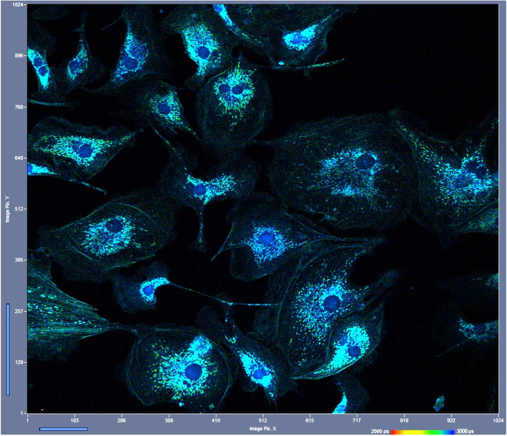
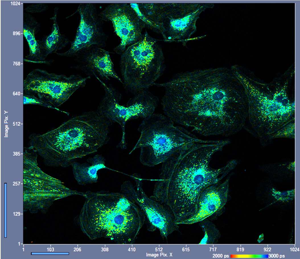
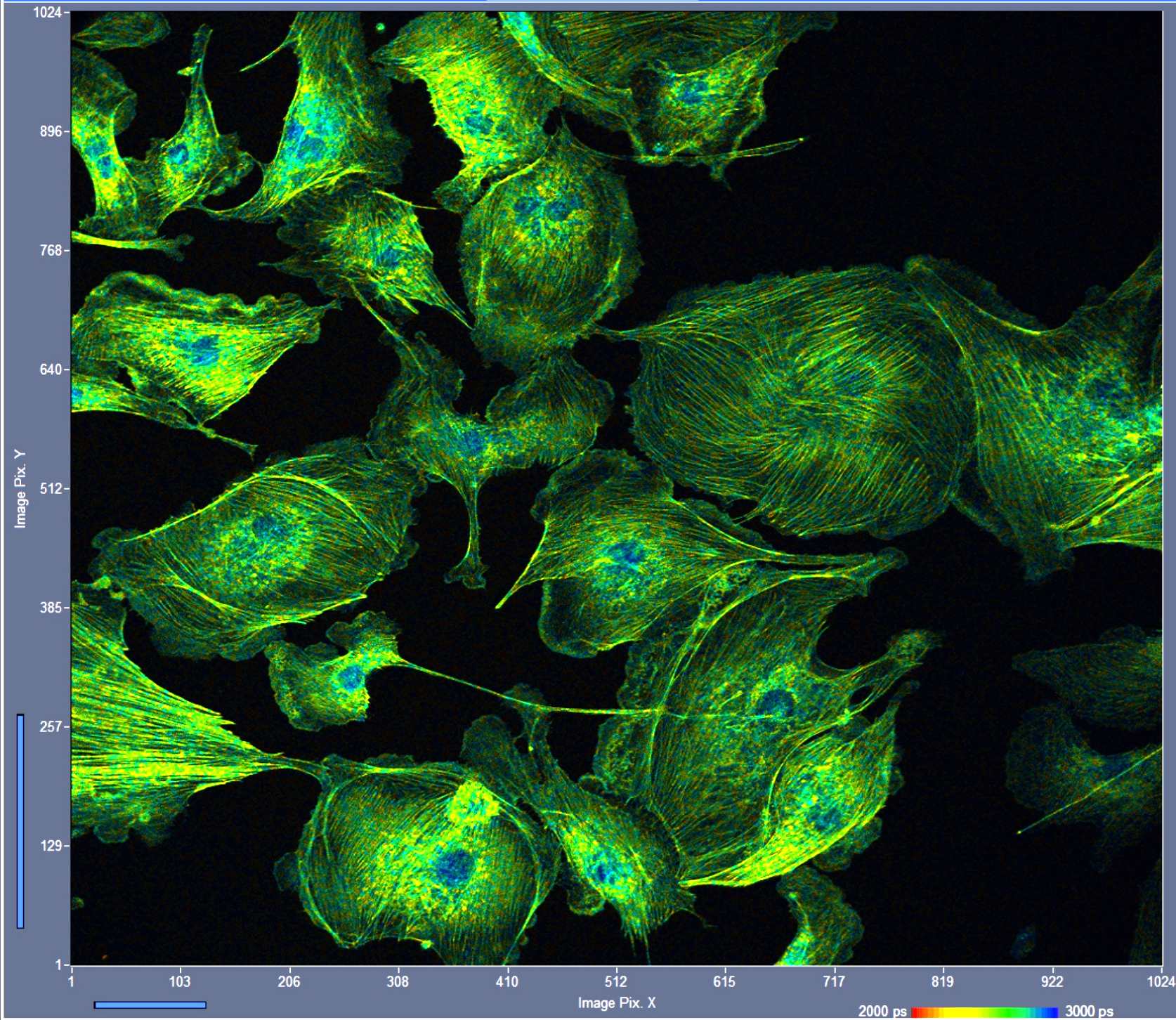
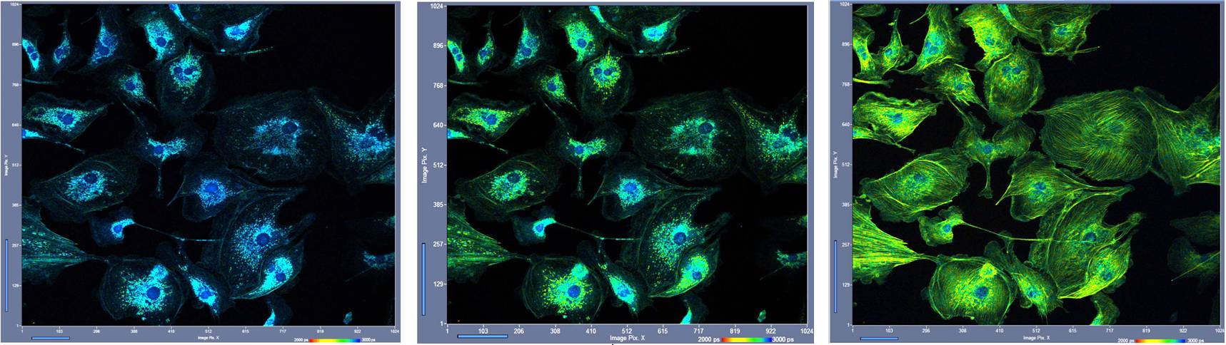
The SPC-QC-104 TCSPC / FLIM module has three parallel TCSPC / FLIM channels with a common reference channel on a single PCI-express board. Alternatively, the module can be operated with four absolute photon timing channels. The module features high temporal and spatial resolution, high peak count rate, and extraordinarily high timing stability. The SPC-QC offers the usual modes for recording temporal waveforms of optical signals, sequential recording multi-wavelength recording, time- and parameter-tag recording, FLIM, spatial and temporal mosaic FLIM, triggered accumulation of fast time series of curves and images, and simultaneous FLIM / PLIM. The SPC-QC runs under bh's SPCM TCSPC/FLIM data acquisition and control software. Data analysis is performed by bh's SPCImage NG software. An example for parallel recording of three FLIM images is shown in the figure below.
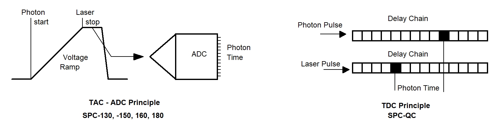
Conversion Principle
Different than the SPC-130, -150, -160 and -180 TCSPC modules, which use a TAC/ADC principle, the SPC-QC uses direct time-to-digital (TDC) conversion. The two principles are illustrated in the figure below. The TAC-ADC principle is shown left. It uses a linear voltage ramp between a start pulse (usually the photon) and a stop pulse (usually a reference pulse from the laser). The voltage is converted in a digital data word which expresses the time of the photon in the laser pulse sequence.
The TDC principle is shown on the right. The photon pulses from the detector(s) and the reference pulses from the laser are sent through chains of delay elements. The timing logics looks at the data in the delay chains, identifies start-stop pairs of photons and laser pulses, and this way determines the temporal positions of the photons in the laser pulse sequence. From these data, the usual TCSPC / FLIM photon distributions are built up.
Comparison with bh SPC-130 to SPC-180 series
The advantage of the TDC principle is that the timing electronics can be implemented in an FPGA (Field-Programmable Gate Array). Therefore several recording channels can be implemented on one TCSPC board. Another feature where the TDC is superior to the TAC is that the TDC principle works up to extremely high count rates. Even the detection of several photons per laser pulse is possible. In practice, the count rate is limited by pile-up, dead time in the detector-discriminator combination, degradation of the detector timing performance at high count rate, and, of course, by the capability of the sample to deliver the count rate without photo degradation.
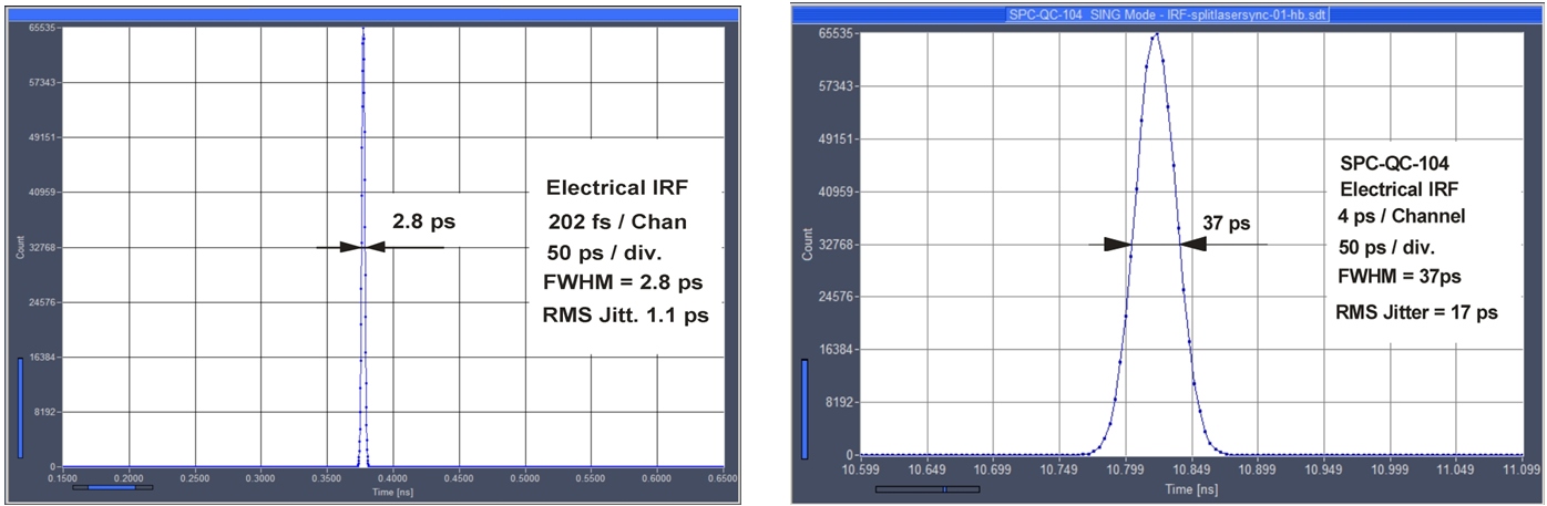
On the downside, the time resolution is much lower than for the TAC ADC principle. A comparison of the electrical IRF of an SPC-180NXX and an SPC-QC-104 is given in the figure below. The IRF width for the SPC-180NXX (left) is 2.8 ps FWHM, for the SPC-QC-104 (right) it is 39 ps FWHM. Although 39 ps FWHM is an excellent value for a TDC the SPC-QC-104 does not exploit the full time resolution of ultra-fast detector, such as SSPDs, MCP-PMTs and ultra-fast hybrid detectors.
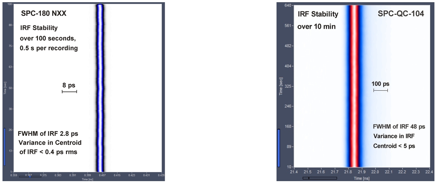
Another critical feature is timing stability. For many years stability was a problem for the TDC. In the SPC-QC-104 the stability problem has largely been overcome by a new TDC-logics structure. A comparison of the timing stability of an SPC-180 NXX and an SPC-QC-104 is shown in the figure below. For the SPC-180 NXX the stability of the first moment of the IRF is better than 0.4 ps RMS, for the SPC-QC-104 it is better than 5 ps RMS (note different time scales). Although the SPC-QC does not reach the stability of the SPC-180NXX possible timing drift remains far below the IRF width and thus is rarely a problem in practical application.
Summary
The SPC-QC-104 is a TDC-based TCSPC FLIM module. It has three parallel TCSPC/FLIM channels and one common reference channel. Alternatively, the modules can be operated with four parallel absolute photon timing channels. The module features high peak count rate and reasonably fast time resolution. With an electrical IRF width of <39 ps FWHM, an internal timing jitter of <19 ps RMS and a timing stability of 5 ps RMS the SPC-QC-104 can be used for a large number of fluorescence decay and FLIM applications. The SPC-QC-104 is especially attractive in applications where several parallel detection channels are desirable, and multi-module systems of SPC-150 or -180 modules appear too bulky or too power consuming. On the downside, the SPC-QC-104 does not exploit the full time resolution of ultra-fast single-photon detectors, such as SSPDs, MCP-PMTs or hybrid PMTs. In applications with such detectors the bh SPC series, preferably the SPC-150NX, SPC-150 NXX, SPC-180NX, or SPC-180NXX should be used.
Gallery