Quick start: choosing your TAC settings
Always start with gain = 1, TAC offset = 0; set range to laser period.
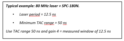
If the laser period is smaller than the minimum TAC Range, set the minimum range and observe that the full decay curve is visible. If not, adjust the cable delay.
- Use the noise floor as an indicator of where your measurement window is, change the cable delay to set the start of the decay curve close to the start of the noise floor.
- Increase the gain until the time axis matches your laser period.
- Use the TAC offset to bring the signal + noise floor into the measured window.
What does the TAC do?
TAC stands for Time to Amplitude Converter. This function is performed by an analogue hardware unit, guaranteeing precision and electronical jitter performance beyond conventional digital solutions.
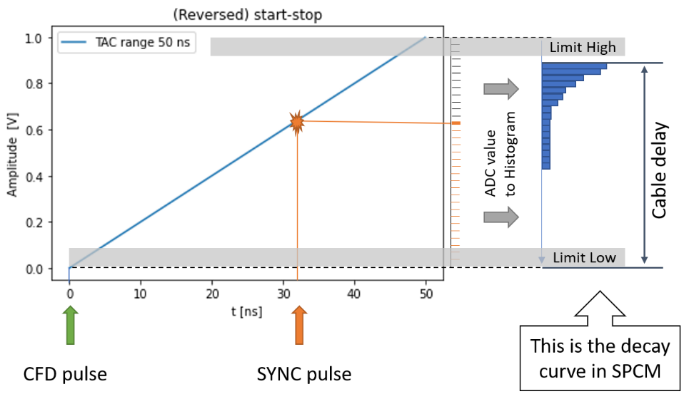
Upon receiving a start signal, a voltage is ramped up. When the stop pulse arrives, the voltage is read. The resulting voltage is proportional to the time difference between start and stop.
Start and stop are defined by SYNC and CFD pulses or vice versa in ‘reversed‘ mode.
Parameters:
- Range = how long until the maximal voltage is reached. This is the slope of the TAC voltage characteristic:
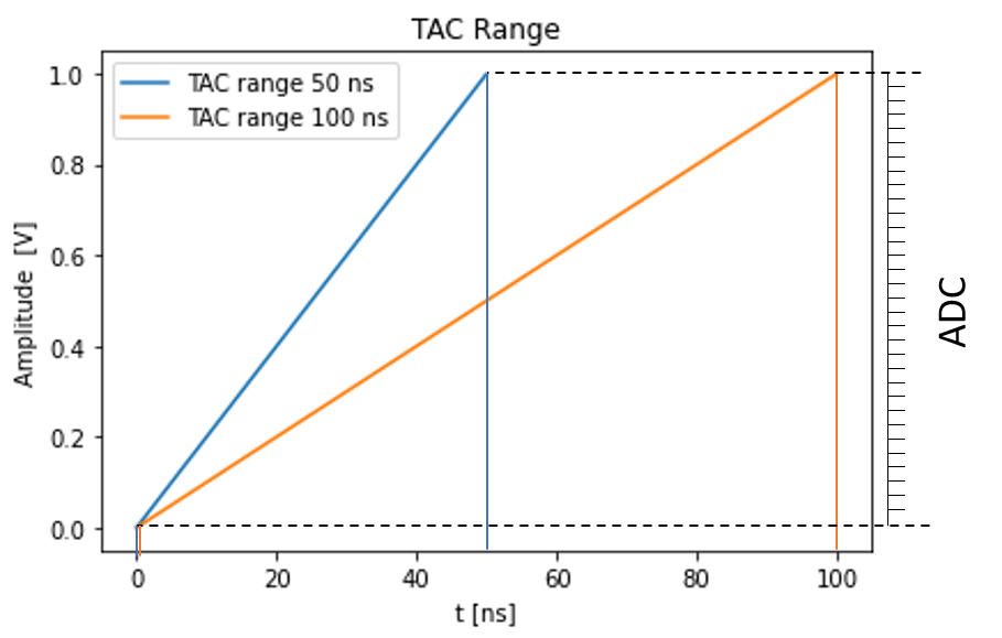
- ADC resolution = the resolution of the analog to digital converter. The ADC encodes a set input voltage range into digital values.
- Gain = amplification of the output voltage to fit small time/voltage ranges onto the entire ADC input capability. Enhances time resolution:
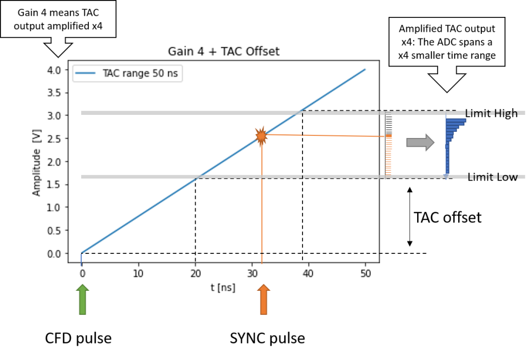
- Offset = at gain > 1 this defines the region of the TAC curve sent to the ADC.
- Limit high = software cap to the ADC range in % (default 100 %).
- Limit low = software cap to the beginning of the ADC range in % (default 0 %).