New SPCM Version 9.78 Comes
With New Software Functions
Abstract: This application note describes new functions implemented
in Version 9.78 of the bh SPCM software [1]. Version 9.78 especially addresses the needs of bhs
Fast-Acquisition FLIM system [3]. FLIM data from up to four TCSPC modules can be
combined into a single FLIM data set, and displayed as gated intensity images
or as lifetime images. Moreover, decay curves can be selected from ROIs or POIs
within the images, and displayed online in a separate decay curve window.
Combination
of Data from Several SPC Modules
Many bh TCSPC and FLIM systems use several
parallel TCSPC modules to record data in several wavelength channels, different
polarisation channels, or from different source positions at an object of large
spatial extension [1]. Multi-module systems are also used to increase the
throughput rate of a TCSPC system. In this case, a single optical signal is either
spread on several detectors the signals of which are recorded in parallel TCSPC
channels [1, 5], or the photon pulses of a single detector are
distributed into four parallel TCSPC FLIM channels [3, 4, 5]. SPCM Version 9.78 has a function to combine the
data of these channels and to display intensity or lifetime images of the
combined data. To activate the channel-combination function select the FIFO
Imaging Mode and open the 3D Trace Parameters. Under Module select M1-4.
Leave the other definitions as they are. Data Type is PS, Display Mode is
F(x,y), see Fig. 1.
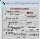
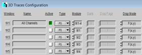
Fig. 1: Combination of TCSPC channels. Left: Measurement control section
of the SPCM System Parameters. Right: 3D Display Parameters
Selecting a channel combination does not
discard the data of the individual channels - it acts only on the display of
the data and on how SPCM interprets the data. A Save operation will save the
original channel data, independently of what is defined in the 3D trace
parameters.
Intensity
Images from Combined Channels
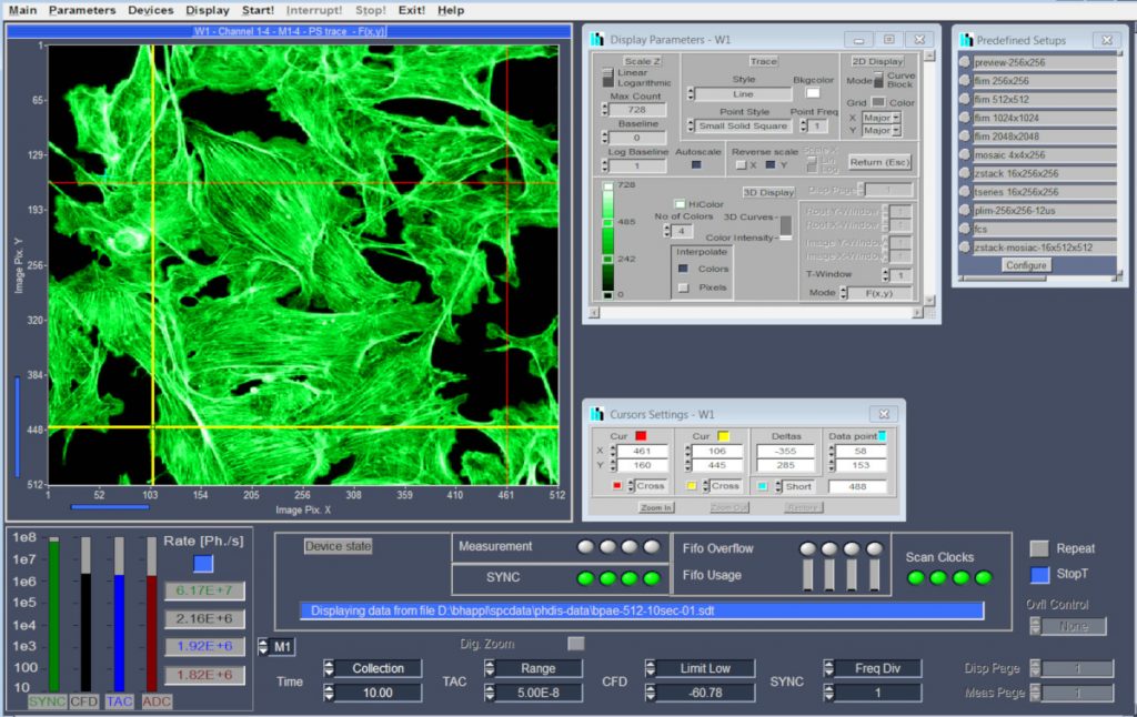
SPCM is able to display (time-gated) intensity
images or colour-coded lifetime images [1]. The result of the settings shown above is a main
panel as shown in Fig. 2, with an image showing a (time-gated) intensity image
of the combined data of SPC modules 1 to 4. Several such images can be
displayed for different time gates, please see [1], [5] or [6] for details. In addition to the combined data, it is
possible to display also the data of the individual channels. To do so,
activate the active buttons for the individual TCSPC modules, M1, M2, M3, M4,
in the 3D Trace definitions. Please see Fig.
5and Fig.
6.
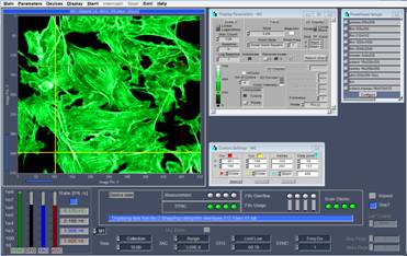
Fig. 2: Main panel, display of the combined data of four TCSPC FLIM
Channels
Lifetime
Images from Combined Channels
The channel-combination function works also
in combination with online lifetime-image display [1, 2]. The trace parameters are shown in Fig. 3. Data Type is LIFET, the data of TCSPC Modules M1-4
are combined into one image.
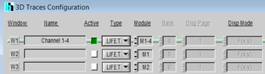
Fig. 3: 3D Trace Parameters for
lifetime image display of combined channels
The corresponding main panel is shown in Fig. 4. The Display Parameter panel is open on the right. In
its lower part it contains the definitions for the lifetime range, the
reference lifetime, binning, and brightness and contrast settings, please see [1] for details.
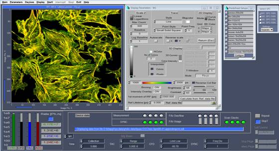
Fig. 4: SPCM Main
panel with lifetime display of combined channels
SPCM is able to display up to eight images
of different data type and/or from different TCSPC modules simultaneously. With
the trace parameters shown in Fig.
5, a lifetime image of four combined channels is
displayed together with the lifetime images of the individual channels. An SPCM
main panel for this configuration is shown in Fig.
6.
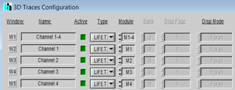
Fig. 5: 3D trace parameters for display of combined channels together with
images of individual modules
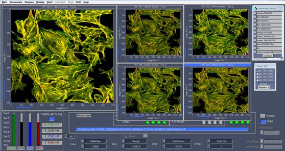
Fig. 6: Main panel with combined images of Channel 1-4 and images of
individual channels
Display
of Decay Data in Point or Region of Interest
A right-mouse click into one of the image
windows of SPCM opens a small panel from where you can access the image
cursors, the display parameters, trace parameters, window parameters, etc. A
click into Show Decays opens a decay-curve window as shown in Fig. 7, right.
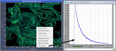
Fig. 7: A right mouse click into an image and a click on Show Decays opens
the decay curve panel shown on the right
The SPCM main panel with the decay curve
window is shown in Fig. 8. The curves can be displayed for all active image
windows, and for individual regions or points of interest (ROIs or POIs). The
ROIs are defined by the image cursors, the POI by the Data Point. A right
mouse click into the decay window opens a panel with the Trace Parameters for
the individual curves. The panel can be seen in Fig. 8, lower right. You can add or remove curves, activate
or de-activate curves, define colours for the curves, define whether a curve is
from an ROI or a POI, and from which image display window the curve comes. The
coordinates of the POI and of the ROI cursors are displayed on the right. As an
example, Fig. 8 displays a lifetime images of the combined channels
of a four-channel-fast acquisition system (large image), the lifetime images of
the individual channels (small images), and the decay data in an ROI of the combined
channels and the individual channels.
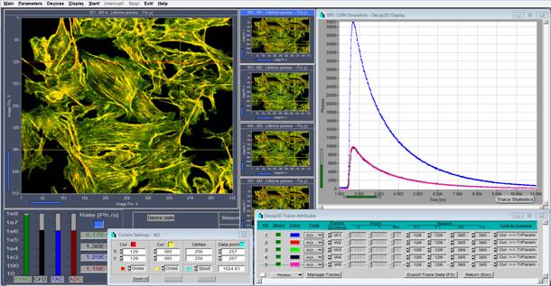
Fig. 8: SPCM Main
Panel with lifetime images and decay curve window
The decay-curve display works for all
images that contain decay data in their pixels. These can be intensity images,
time-gated intensity images, lifetime images, combined images from several
TCSPC modules, or images from different routing channels of a TCSPC module.
The display of the decay curves itself is
controlled by the Display Parameters the same way as for decay curves
recorded in the Single, Oscilloscope, or FIFO mode. The display scale can
be linear or logarithmic, an autoscale function is available, and the curves
can be displayed as individual data points, lines, or data points connected by
lines. Please see software description in the bh TCSPC Handbook [1] or in the handbooks of the DCS-120 FLIM system [5] or of the FLIM systems for the Zeiss
LSM 710/780/880 family microscopes [6].
Other
New SPCM Features
There are
other new SPCM features which have already been added in previous software
versions. For example, SPCM is able to control Ti:Sa lasers and the bh AOM
module [1]. Ti:Sa and AOM control is used in the
DCS-120 MP multiphoton FLIM microscopes, please see [5]. The features can, however, also
be used for user-built two-photon microscopes and for other Ti:Sa applications.
Control of a motorised sample stage has been implemented in SPCM version 9.76.
In combination with the bh DCS-120 confocal and multiphoton scanning FLIM
systems, the stage is used to record mosaics of FLIM images and to control the
microscope remotely. Please see [1] and [5].
References
1.
W. Becker, The bh TCSPC
handbook. Becker & Hickl GmbH, 7th ed. (2017). Available on
www.becker-hickl.com
2.
Becker & Hickl GmbH, SPCM
Software Runs Online-FLIM at 10 Images per Second. Application note, available
on www.becker-hickl.com
3.
Becker & Hickl GmbH, Fast-Acquisition
TCSPC FLIM System with sub-25 ps IRF Width. Application note, available on
www.becker-hickl.com
4.
Becker & Hickl GmbH, Fast-Acquisition
Multiphoton FLIM with the Zeiss LSM 880 NLO. Application note, available on
www.becker-hickl.com
5.
Becker & Hickl GmbH, Fast-Acquisition
TCSPC FLIM: What are the Options? Application note, available on
www.becker-hickl.com
6.
Becker & Hickl GmbH,
DCS-120 confocal and multiphoton FLIM systems. User Handbook, available on
www.becker-hickl.com
7.
Becker & Hickl GmbH, FLIM
systems for Zeiss LSM 710/780/880 family microscopes. User Handbook, available
on www.becker-hickl.com