SPC Modules Record FLIM with Bidirectional Scanning
Wolfgang Becker,
Stefan Smietana, Becker & Hickl GmbH
Abstract: With
Version 9.73 SPCM Software, the bh TCSPC / FLIM systems are able to record FLIM
with bidirectional scanning. As usual, data recording is synchronised with the
scanning by frame clock, line clock, and pixel clock pulses from the scanner. Each
first line clock pulse indicates the beginning of a forward scan, each second
one the beginning of a backward scan. The recording procedure automatically
reverses the data from the backward scan and compensates for the line shift
caused by the dynamic behaviour of the scanner. The FLIM data structure is the
same as for unidirectional scanning. Thus, standard online intensity and
lifetime display functions of the SPCM software are available, and data can be
analysed by SPCImage as usual.
Bidirectional Versus Unidirectional Scanning
There are two different ways to raster-scan
a sample in a laser scanning microscope. Unidirectional scanning uses a linear
forwards scan and a fast flyback. Data are recorded only during the forward
scan. Bidirectional scanning uses a linear scan in both directions, and records
data both during the forward and the backward scan. The differences are shown
in Fig. 1.

Fig. 1:
Unidirectional scan (left) and bidirectional scan (right)
At first glance, a bidirectional scanning
appears far more efficient than a unidirectional one. No time has to be wasted
for the flyback, the acceleration forces acting on the scan mirrors are lower,
and there is no need to turn off the excitation laser during the beam flyback.
However, these advantages come at a price. Due to dynamic effects, there is a
lag (or phase shift) of the scanner position behind the scanner control
voltage. The result is a horizontal shift of the image data between the forward
scan and the backward scan. The size of the shift depends on the scan speed and
is thus not easy to correct. Moreover, the horizontal scan must be linear (or
at least symmetrical) within 0.1% of the image size to avoid a mismatch of the
forward and backward scan data. This is not easy to achieve, especially if high
scan rates are desired. A unidirectional scan does not have these problems. The
scanner lag does not matter and a much larger nonlinearity can be tolerated.
The beam flyback can be made much faster than the forward scan. Even for the
fastest scan rates, it normally requires no more than 10% to 20% of the line
time [2]. The speed advantage of a bidirectional scan is therefore smaller than
commonly believed. Nevertheless, almost all laser scanning microscopes and a
number of clinical scanning systems have a bidirectional scan implemented, or
offer it at least as an option. A FLIM system attached to these systems should
therefore be able to record data with a bidirectional scan.
Implementation in the SPCM Software
FLIM recording by bidirectional scanning
has been implemented in SPCM software, version 7.93. It is available in the
FIFO Imaging mode, see Fig. 2, left. The scan parameter definitions are shown
in Fig. 2, right.
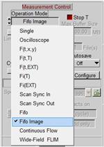

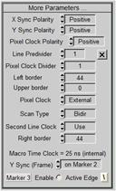
Fig. 2: SPCM system parameters for bidirectional
scanning. Left: Measurement control section of system parameters, FIFO
Imaging Mode is selected. Middle: Page Control section, Image pixels X and X
should be set according to the pixel format of the scanner. Right: More
Parameters panel, accessible by clicking on More Parameters in the SPCM
system parameters. Bidirectional scanning is selected by Scan Type = Bidir,
the line shift is corrected by Left Border and Right Border
Operation Mode must be FIFO Imaging [1, 4],
see Fig. 2, left. Image Pixels X and Image Pixels Y (Fig. 2, middle) should
be set to the number of pixels in the microscope scan. The parameters which
synchronise the FLIM recording with the scanning are defined in the
More-Parameters panel (click on the More Parameters button to open it). To
activate bidirectional recording, set Scan Type to Bidir. Second Line
Clock must be set to Use. The line clock at the beginning of the backward
scan then starts the recording of each second line, and reverses the direction
of recording from forward to backward. The Left Border and Right Border
parameters delay the recording of the data within each line by the defined
number of pixels. The borders are used to correct for the line shift caused by
the lag of the scanner. The correct values have to be determined
experimentally. Please note that the scanner lag (and thus the values of the
parameters) depend on the scan speed. You may thus need different scan
parameter sets for different scan speeds. Please remember that you can put
these setups in the Predefined Setups panel, from where they can be loaded by
a single mouse click.
The other parameters are the same as for
unidirectional scanning. Polarity defines the polarity of the scan clocks,
the line and pixel clock predividers bin several lines and pixels into a single
line or pixels of the result. Use divider settings of 1 for bidirectional
scanning. Please refer to [1] for details.
Results
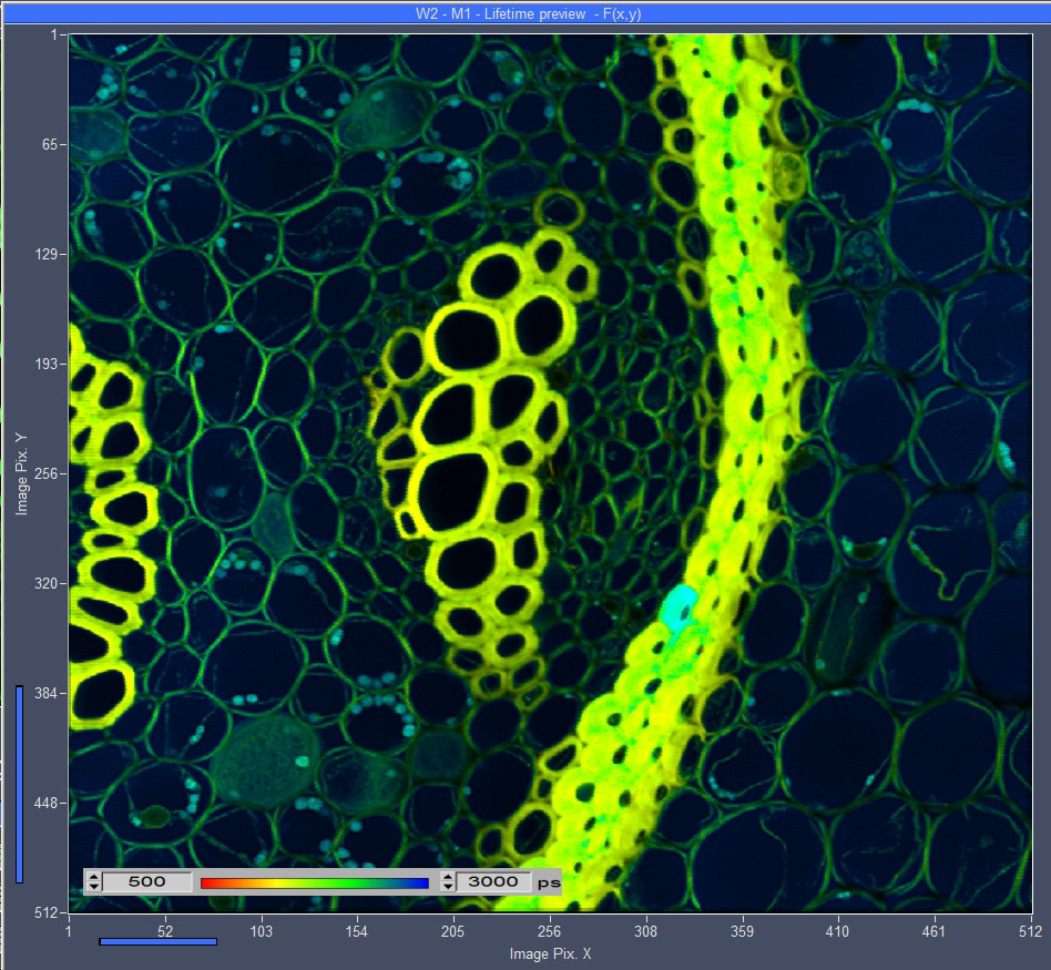
FLIM data recorded by bidirectional
scanning are shown in Fig. 3, left and right. The data were recorded by a bh Simple-Tau
152 FLIM system [1], with two SPC-150 TCSPC FLIM modules, in combination with a
Zeiss LSM 880 [3]. The sample was excited by the 445 nm ps diode laser of
the LSM880, the fluorescence was recorded via the confocal port of the scan
head. The image on the left shows a convallaria sample scanned with 512x512
pixels, the image on the right a BPAE cell sample scanned with 1024x1024
pixels. Both were calculated by the online-lifetime function of the SPCM
software [5]. No double structure or blurring of details is visible, showing
that the data from the forward scan perfectly match those from the backward
scan.
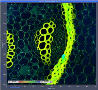
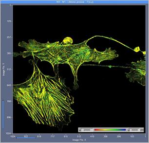
Fig. 3: Convallaria sample (left, 512x512 pixels) and BPAE Cell sample
(right, 1024x1024 pixels), recorded with bidirectional scanning. SPC-150 TCSPC
module, Zeiss LSM 880 in bidirectional scan mode. One-photon excitation at
445 nm. Images from online-lifetime function of SPCM software [5].
Fig. 4 shows the Convallaria data of Fig. 3,
left, analysed by bh SPCImage FLIM data analysis software. No special adjustment
was used, the data were just analysed as described in [1, 2, 3].
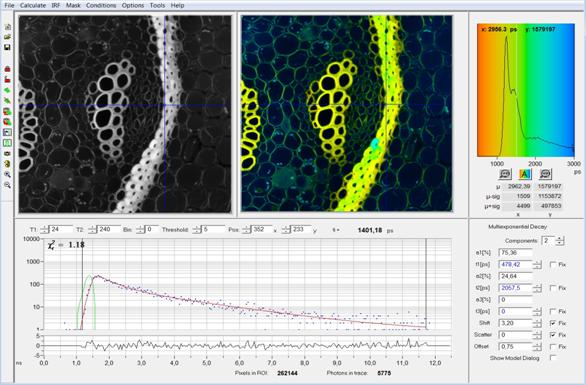
Fig. 4: Convallaria
sample data as in Fig. 3, left, analysed with SPCImage. Double-exponential
decay model, intensity-weighted lifetime of decay components.
Summary
FLIM data recording in combination with
bidirectional scanning became available with Version 9.73 of the bh SPCM
software. The data are recorded in the FIFO imaging mode [1, 4], the
synchronisation of the recording with the scanning is defined in the More
Parameters panel of the SPCM system parameters [1]. Bidirectional recording
works for all bh TCSPC modules which have the FIFO Imaging (software
accumulation) mode implemented. That means the function is available for all
SPC-150, SPC-150N, SPC-160 and SPC-160pcie modules, and for SPC‑830
modules manufactured later than May 2007 [4]. The structure of the data
recorded is the same as for unidirectional scanning, and the same pixel numbers
and time channel numbers can be achieved [6]. The online intensity [1] and
lifetime image [5] display functions of the SPCM software are available, and
the recorded data can be analysed by bh SPCIMage FLIM data analysis software as
usual [1, 2, 3].
References
1. W. Becker, The bh TCSPC handbook. 9th edition, Becker & Hickl
GmbH (2021), available on www.becker-hickl.com
2. Becker & Hickl GmbH, DCS-120 Confocal Scanning FLIM Systems, 6th
ed. (2015), user handbook. www.becker-hickl.com
3. Becker & Hickl GmbH, Modular FLIM systems for Zeiss
LSM 710 / 780 / 880 family laser scanning microscopes. 6th ed. (2015),
user handbook. available on www.becker-hickl.com
4. Becker & Hickl GmbH, FLIM in the FIFO Imaging Mode: Large
Images with Small TCSPC Modules. Application note, available on
www.becker-hickl.com
5. Becker & Hickl GmbH, SPCM Software Runs Online-FLIM at 10
Images per Second. Application note, available on www.becker-hickl.com
6.
H. Studier, W. Becker, Megapixel FLIM. Proc.
SPIE 8948 (2014)
Contact:
Wolfgang Becker, becker@becker-hickl.com