The HPM‑100-40
Hybrid Detector
Wolfgang
Becker, Becker & Hickl GmbH
The bh HPM‑100 module combines a
Hamamatsu R10467-40 GaAsP hybrid PMT tube with the preamplifier and the
generators for the PMT operating voltages in one compact housing. The principle
of the hybrid PMT in combination with the GaAsP cathode of the R10467-40 yields
excellent timing resolution, a clean TCSPC instrument response function, high
detection quantum efficiency, and extremely low afterpulsing probability. The
virtual absence of afterpulsing results in a substantially increased dynamic
range for fluorescence decay recordings. FCS curves down to 100 ns
correlation time can be obtained from a single detector, without the need of
cross-correlation. The HPM‑100 module is operated via the bh DCC-100
detector controller of the bh TCSPC systems.
Principle
The basic principle of a hybrid PMT is
shown in Fig. 1. The photoelectrons emitted by a photocathode are accelerated
by a strong electrical field and injected directly into a silicon avalanche
diode [4, 8].
Fig. 1: Principle of a hybrid PMT
When an accelerated photoelectron hits the
avalanche diode it generates a large number of electron-hole pairs in the
silicon. These carriers are further amplified by the linear gain of the
avalanche diode. The principle of the hybrid PMT has a number of advantages
over other detector principles.
An obvious advantage of the hybrid PMT is
that a large part of the gain is obtained in a single step. Hybrid PMTs
therefore deliver single-photon pulses with a narrow amplitude distribution.
The devices can thus be used to distinguish between one, two, or even more
photons detected simultaneously [8 La Rue Photon
counting hybrid 1060-nm... IEEE Electron Device Letters 20 No. 3 (1999)
126-128; La Rue Photon counting III-V hybrid... IEEE Transactions on Electron
Devices 44 No. 4 1997 672-678]. In TCSPC applications the low amplitude
fluctuation virtually eliminates the influence of the CFD circuitry on the
timing jitter.
More important for TCSPC, the high
acceleration voltage between the photocathode and the APD results in low
transit time spread [4]. With an acceleration voltage of 8 kV the
transit-time spread of the electron time-of-flight is only 50 ps [4, 5]. Moreover, the TCSPC instrument
response of a hybrid PMP is very clean, without significant tails, bumps, or
secondary peaks.
Compared to a conventional PMT, the hybrid
PMT has also an advantage in terms of counting efficiency. In a conventional
PMT, a fraction of the photoelectrons is lost on the first dynode of the
electron multiplication system [1]. Instead of being multiplied electrons may
also get absorbed or reflected. There are no such losses in the hybrid PMT: A photoelectron
accelerated to an energy of 8 keV is almost certain to generate a signal
in the avalanche diode. With a high-efficiency GaAsP cathode a hybrid
photomultiplier reaches the efficiency of a single-photon APD (SPAD), but with
a cathode area several orders of magnitude larger.
The perhaps most significant advantage of
the hybrid PMT has been recognised only recently: The hybrid PMT is virtually
free of afterpulsing [xxx]. Afterpulsing is the major source of counting
background in high-repetition-rate TCSPC applications, and a known problem in fluorescence
correlation measurements. Background has a detrimental effect on the accuracy
of fluorescence lifetime determination [6]. Afterpulsing in FCS results in a false
peak at correlation times shorter than a few µs. So far, the afterpulsing peak
could only be suppressed by splitting the light and recording cross-correlation
between two detectors.
The absence of afterpulsing in a hybrid PMT
is inherent to its design principle. In conventional PMTs afterpulsing is
caused by ionisation of residual gas molecules by the electron cloud in the
dynode system. In single-photon avalanche photodiodes afterpulsing results from
trapped carriers of the previous avalanche breakdown. Both effects do not exist
in the hybrid PMT: Ionisation is negligible because only single electrons are
travelling in the vacuum, and there is no avalanche breakdown in the APD.
On the downside, there are also a few
disadvantages of the hybrid PMT. The extremely high cathode voltage is
difficult to handle. It can be a problem especially in clinical biomedical
applications. The APD reverse voltage must be very stable, and be correctly
adjusted. The most significant problem is the low gain of the hybrid PMTs.
Earlier devices reached a gain on the order of only 104. At a gain
this low, the single-photon pulse amplitude is in the µV range. Therefore
electronic noise from the termination resistor and from the preamplifier
impaired the time resolution of single photon detection. Until recently, hybrid
PMTs were therefore not routinely used for TCSPC experiments. The situation
changed with the introduction of the R10467 hybrid PMTs of Hamamatsu [5]. The devices reach a total gain on the
order of 105. The single-photon pulse amplitude is on the order of
several 100 µV, the pulse width about 800 ps. A high bandwidth,
low-noise preamplifier is able to amplify the pulses into an amplitude range
where they are detected by the constant-fraction discriminator of a bh TCSPC
module. Initial tests have shown the superior performance of the R10467 compared to previously existing detectors [2]. However, in
practice RF noise pickup from the environment, noise from the high voltage
power supplies, and low-frequency currents flowing through ground loops make
the bare R10467 tube difficult to use in TCSPC experiments.
The bh HPM‑100 Hybrid Detector Module
To make the R10467 applicable to standard
TCSPC experiments bh have integrated the R10467 tube, the power supply for the
cathode voltage, the power supply for the APD voltage, and the preamplifier in
a compact, carefully shielded detector module. The device is shown in Fig. 2.
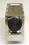
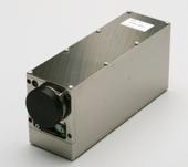
Fig. 2: bh HPM‑100 hybrid PMT module. The module contains the Hamamatsu
R10467 hybrid PMT tube, the generators for the cathode voltage and the APD reverse
voltage, and the preamplifier. The module is operated via the DCC‑100
card of the bh TCSPC systems (right)
The housing has separate compartments for
the voltage generators, the R10467 tube, and the preamplifier. These are shielded
and decoupled against each other and the environment. The complete module is
operated via the bh DCC‑100 detector controller card. The DCC‑100
provides for power supply, control of the APD reverse voltage, and overload
shutdown. One DCC‑100 card can control two HPM‑100 hybrid PMT
modules.
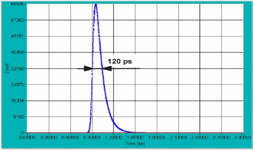
Instrument response function
The instrument response function of an HPM‑100-40
with an R10467-40 tube is shown in Fig. 3.
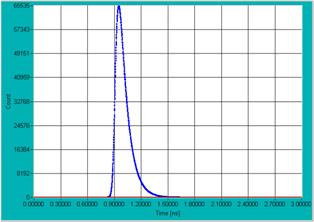
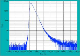
Fig. 3: Instrument response function of the HPM‑100-40. Left: linear
scale. Right: Logarithmic scale. BDL‑445 SMC picosecond diode laser,
bh SPC‑830 TCSPC module.
The recorded instrument response function
(IRF) width is 130 ps. Corrected for the laser pulse width of 60 ps
the IRF width is about 120 ps. The response function is remarkably clean,
as can be seen in the logarithmic plot on the right. It should be noted that
the transit time spread and thus the IRF width of the R10467-40 is dominated by
the internal time constants of its GaAsP cathode. The R10467-06 tube (with a
conventional bialkali cathode) is faster, with an IRF width of about
50 ps.
Afterpulsing
The afterpulsing is characterised best by
the autocorrelation function of the photons of a continuous light signal detected
at a known count rate [1, 2]. Fig. 4 compares the autocorrelation function of
an HPM‑100-40 at 10 kHz count rate with that obtained by a Hamamatsu
H5773-1 photosensor module. The autocorrelation for the HPM is flat down to the
dead time of the SPC‑830 module used. Comparable performance has been
achieved so far only for NbN superconducting detectors. These detectors have
active areas with µm extensions and need to be operated in a liquid-He cryostat
[9].
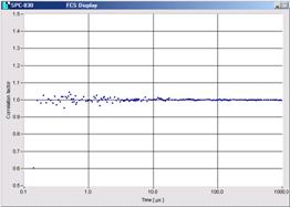
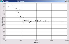
Fig. 4: Autocorrelation function of a continuous light signal of
10 kHz count rate. Left: HPM‑100-40. Right: H5773-1. The
autocorrelation function measured with the HPM is flat down to 125 ns,
indicating that no afterpulses are detected.
Fig. 5 shows an FCS curve measured for a
solution of fluorescein in water. The data were recorded by an HPM‑100-40
connected to the bh DCS‑120 confocal scanning FLIM system [3]. Because
there is no afterpulsing peak diffusion and triplet times are obtained by
autocorrelation of the photons detected in a single detector.

Fig. 5: Fluorescence correlation function of fluorescein molecules in
water. Recorded with HPM‑100-40, connected to bh DCS‑120 confocal
scanning FLIM system
The low afterpulsing results in a
significantly improved dynamic range of fluorescence decay measurements. An
example is shown in Fig. 6. It shows the fluorescence decay of fluorescein
recorded at a laser repetition rate of 20 MHz. The signal was detected by
a HPM‑100-40 (left) and a H5773-1 photosensor module (right). Both
detectors have approximately the same dark count rates.
For the HPM‑100, the dark count rate
is the only source of background. Because the dark count rate is only a few 100
counts per second an extraordinarily high dynamic range is obtained. For the
H5773-1 the background is dominated by afterpulsing. The background is
substantially higher, and the dynamic range is far smaller than for the HPM‑100.
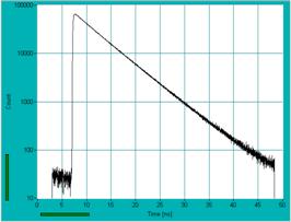
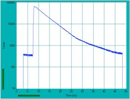
Fig. 6: Fluorescence decay curves for fluorescein recorded at a laser
repetition rate of 20 MHz. Left: HPM‑100-40. Right: H5773-01
Sensitivity
We had no possibility to verify the
detection quantum efficiency of the R10467-40 quantitatively. The curve of
cathode quantum efficiency versus wavelength shown in Fig. 7, left, was
therefore copied from the specifications of Hamamatsu [5]. What we could
verify, however, is that the detection efficiency surpasses the efficiency for
the Hamamatsu H7422P-40. The H7422P-40 has the same cathode type but uses a
conventional PMT design. Until now, the H7422P-40 was the ultimate in
sensitivity for visible-range PMTs. The HPM reaches at least the same
efficiency, but at a far better time resolution and without any afterpulsing.
Fig. 7: Left: Detection quantum efficiency according to Hamamatsu
specification. Right: Dark count rate. Black curve average of 4 detectors.
Yellow area: Range of variation for 7 detectors, measured over several days.
For low-level light detection the limiting parameter
is often not only the efficiency but also the dark count rate. Typical curves of
the dark count rate versus temperature are shown in Fig. 7, right. The values we
found are a bit lower than the numbers in the Hamamatsu test sheets, and
significantly lower that the numbers given in [7]. The reasons are not clear.
It should be noted that low dark count rates are only obtained if (a) the reverse
voltage of the avalanche diode is selected below the breakdown level and (b)
the tube has been kept in darkness for several hours after any exposure to
daylight.
The advantage of large active area
In most applications it is difficult or
even impossible to concentrate the light to be detected on an extremely small
area. A typical case is multiphoton microscopy. Multiphoton microscopy is used
to obtain images from image planes deep in a sample. The fluorescence photons
from these layers are scattered on the way out of the sample and emerge from a
large area of the sample surface. Although these photons can be transferred to
a detector by non-descanned detection they cannot be concentrated on an area
smaller than a few mm in diameter [1, 2].
A similar situation can exist even in a
confocal microscope. Confocal detection uses a pinhole in a plane conjugate
with the image plane in the sample [3]. One would expect that the light from
the pinhole is easy to focus an a small detector, such as a single-photon
avalanche diode (SPAD). Unfortunately, in practice this is often not the case.
Normally scan heads of laser scanning microscopes have additional magnification
built in so that the physical pinhole size in on the order of millimeters.
Demagnifying the pinhole to the size of a SPAD by a single lens can be
impossible. This is especially the case when larger pinholes, on the order of
tens of Airy Units, are used.
An example is shown in Fig. 8. Both
lifetime images were recorded at a pinhole size of 3 Airy Units. Data recorded
with the HPM‑100 are shown left, data recorded with an id‑100‑50
SPAD right. Despite of the fact that the quantum efficiencies of the detectors do
not differ substantially the image recorded with the HPM contains about twice
the number of photons as the image recorded with the SPAD.
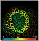

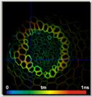
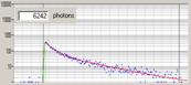
Fig. 8: Fluorescence lifetime images recorded with an HPM‑100 (left)
and with an id‑100‑50 SPAD (right). Images and decay functions at
selected cursor position.
Controlling the HPM‑100-40
The HPM‑100 is operated and
controlled via the DCC‑100 card of the bh TCSPC systems [2]. The DCC
control panel is shown in Fig. 9.
For safety reasons, the DCC‑100 comes
up with all outputs disabled, see Fig. 9, left. Both the acceleration voltage
and the reverse voltage of the avalanche diode (AD) are turned off. The panel
is shown for one detector and for two detectors.
Once the outputs are enabled (Enable
button) and the +12V operating voltage is turned on (+12V button) the internal
high-voltage generator applies the 8 kV acceleration voltage to the R10467
tube and turns on the reverse voltage of the avalanche diode. The +5V and the
-5V must also be turned on, they are used in the preamplifier. The AD reverse
voltage is controlled via the Gain sliders.
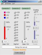
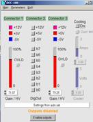
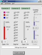
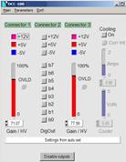
Fig. 9: DCC-100 control panel, for one detector and for two detectors.
Left: After software start, the detectors are disabled. Right: Detectors
enabled. The Gain sliders control the AD voltages.
The correct selection of the operating
parameters is critical to the operation of the HPM. The recommended CFD
threshold of the SPC module is -30 mV. The AD reverse voltage must be
selected to operate the AD close to the maximum stable gain, but not in the
breakdown region.
The selection of the AD voltage is
demonstrated in Fig. 10. The gain of the AD increases steeply with the voltage,
see Fig. 10, left. Consequently, photon counting is obtained in a relatively
narrow interval of the reverse voltage, or DCC Gain. The gain-voltage
characteristics vary for different detectors. Different detectors therefore
need different values of the DCC gain. The correct DCC gain can easily be found
by slowly increasing the DCC gain and observing the count rate displayed by the
TCSPC module. Typical curves of the count rate versus DCC Gain are shown in Fig.
10, right. At low DCC gain no counts are obtained. At a specific DCC gain the
count rate rises steeply. Then it remains almost constant over an interval of 5
to 10 % of DCC Gain. Beyond this interval the count rate rises steeply. The APD
is driven in the breakdown region, the APD current becomes unstable, and eventually
the DCC‑100 shuts the HPM‑100 down. The correct operating point is
in the middle of the flat part of the curve, as indicated in Fig. 10, right.
Fig. 10: Left: General dependence of the AD gain on the AD reverse voltage.
Right: Dependence of the count rate on the DCC Gain for different detectors.
The correct operating point is in the flat part of the curve.
If the AD current becomes too high, either
because the Gain was pulled too far up or the light intensity is too high,
the DCC‑100 shuts down the HPM‑100. The acceleration voltage is
turned off, and the APD reverse voltage is reduced down to zero. This brings
the detector in a safe state. After the reason of the overload has been
removed, the detector can be brought back to operation by clicking on the
Reset button. The DCC-100 panel in the overload state is shown in Fig. 11.
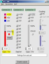
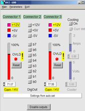
Fig. 11: DCC‑100 panel after overload shutdown. Left one detector.
Right: Two detectors, both detectors shut down.
Summary
With the bh HPM‑100 module, there is,
for the first time, a detector that combines high speed, clean response, high
efficiency, large active area, absence of afterpulsing, and ease of use. Combined
with the bh TCSPC systems, it detects fluorescence decay functions with
unprecedented dynamic range, has the sensitivity to efficiently acquire FCS
data, and delivers FCS without the need of cross-correlation. The main area of
application of the HPM‑100 is time-resolved microscopy which demands for
exactly the combination of parameters the HPM‑100 provides. However, the
HPM‑100 may be used for any TCSPC experiments that require high
precision, high sensitivity, and wide dynamic range.
References
1.
W. Becker, Advanced time-correlated single-photon counting techniques. Springer, Berlin,
Heidelberg, New York, 2005
2. W. Becker, The bh TCSPC handbook. 3rd edition, Becker
& Hickl GmbH (2008), available on www.becker-hickl.com
3.
Becker & Hickl GmbH, DCS-120 Confocal
Scanning FLIM Systems, user handbook. www.becker-hickl.com
4. A. Fukasawa, J. Haba, A. Kageyama, H. Nakazawa and M. Suyama, High
Speed HPD for Photon Counting, 2006 Nuclear Science Symposium, Medical Imaging
Conference, San Diego, CA (2006)
5.
Hamamatsu Photonics, R10467 hybrid PMTs, data sheet.
6. M. Köllner, J. Wolfrum, How many photons are necessary for
fluorescence-lifetime measurements?, Phys. Chem. Lett. 200, 199-204 (1992)
7.
X. Michalet, A. Cheng, J. Antelman, Motohiro
Suyama, Katsuhiro Arisaka, Shimon Weiss, Hybrid photodetector for
single-molecule spectroscopy and microscopy. Proc. SPIE 6862 (2007)
8.
R.A. La Rue, K.A. Costello, G.A. Davis, J.P.
Edgecumbe, V.W. Aebi, Photon Counting III-V Hybrid Photomultipliers Using
Transmission Mode Photocathodes. IEEE Transactions on Electron Devices 44,
672-678 (1997)
9.
M. Stevens, R.H.
Hadfield, R.E. Schwall, S.W. Nam, R.P. Mirin, Time-correlated single-photon
counting with superconducting detectors. Proc. of SPIE 6372, 63720U-1 to -10