Influence of Magnetic Fields on the IRF of High-Speed
Detectors for TCSPC
Abstract: We tested bh HPM hybrid detectors and bh PMCS
PMT detectors for IRF changes induced by external magnetic fields. The effects
were found surprisingly small. For a magnetic-field strength on the order of
100 Gauss the shift in the IRFs was between 1.75 ps and 14.5 ps
compared to the field-free case, depending on the direction of the field. The
FWHM changed from 16.4 ps to 18.4 ps for the HPM and 97 ps to
109 ps for the PMCS.
Motivation
It is commonly known that magnetic fields
influence the detection efficiency and the temporal response of PMTs. For
conventional PMTs the effects are so large that careful magnetic shielding is
recommended. Understandably, users of TCSPC systems with PMTs or other
vacuum-tube detectors are concerned that the temporal instrument-response
function (IRF) of their system may change in the presence of magnetic fields. We
therefore tested the bh HPM hybrid detector modules and the bh PMCS PMT detector
modules for possible IRF changes by externally applied magnetic fields.
Experimental Setup
As a source of the field we used DD2 type
disc magnets from K&J Magnetics, Inc., see Fig. 1, left. The magnet has a
field perpendicular to the plane of the disc, with a surface strength of 1940
Gauss. For the tests we placed the magnet at the outside of the detector under
test. For the HPM detector, the distance of the magnet from the detector axis was
about 25 mm. The field strength in this distance is about 100 Gauss. For
comparison, the magnetic field of the earths is about 0.5 Gauss. The field
strength was calculated by the K&J Magnetic Field Calculator, available
on www.kjmagnetics.comfieldcalculator.asp. The field configuration is shown in
Fig. 1, right.
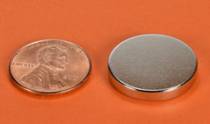
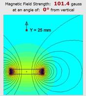
Fig. 1: Left: Magnet used for the test. Right: Field configuration and
field strength at the magnetic axis 25 mm from the magnet . Both figures from
www.kjmagnetics.com
IRF measurements were performed on a bh
HPM-100-07 hybrid detector and a PMCS-150-01 PMT detector. Both detectors
belong to the fastest of their kind. The HPM-100-07 yields an IRF width of
< 20 ps [2]. The IRF with of the PMCs-150 is between 100 ps
and 120 ps, depending on the size of the illuminated spot [1]. Both detectors
have multialkali cathodes. Different than for detectors with GaAsP or GaAs
cathodes, the electron emission from the multi-alkali cathode occurs
instantaneously and thus does not contribute to the IRF. A possible effect of a
magnetic field on the electron trajectories and thus on the IRF therefore
should stand out clearly.
The IRFs were recorded with a bh SPC‑150NX
TCSPC module, with an electrical IRF of about 3.5 ps FWHM [1]. As a test
light source we used a FemtoFibre pro femtosecond-fibre laser from Toptica. The
wavelength is 780 nm, the beam diameter 1.5 mm. The laser beam was attenuated
by a package of ND filters and, without other optical elements, projected to
the photocathode of the detector. The magnets were applied with their magnetic
axis perpendicular to the detector axis and under 45 degrees to it. The test
configurations are shown in Fig. 2.
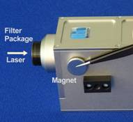
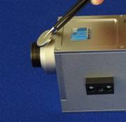
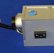
Fig. 2: Magnetic-field configurations tested. Field direction from
detector axis: Left (a) 90 deg horizontal, middle (b) +45 degree vertical, right
(c) -45 degree vertical
Results
The results were a surprise. For none of
the field configurations large changes in the IRF shape and IRF position were
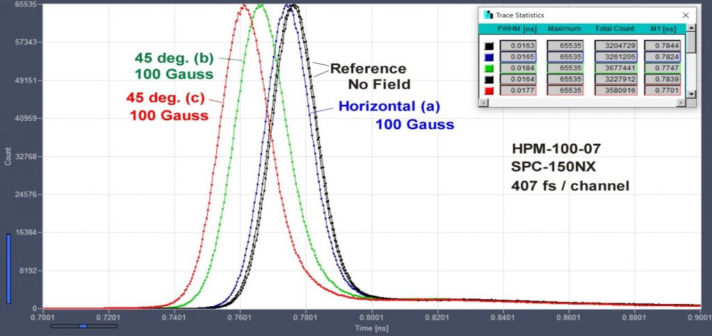
detected. The results for the hybrid detector are shown in Fig. 3. The black
curves are reference curves recorded without the magnetic field. On curve was
recorded at the beginning, the other at the end of the experiments. The FWHM is
16.3 ps and 16.5 ps, an the shift in the first moment is 0.5 ps.
This is within the natural fluctuation by the low-frequency timing wobble of
the laser sync output and the photon timing in the SPC module. The blue curve
shows the IRF for field configuration a, i.e. with the field axis horizontally
and perpendicular to the axis of the detector. The shift in the first moment
versus the averaged reference curves is 1.75 ps, the FWHM is 16.5 ps.
The green and the red curves show the IRF for the +45-degree and -45-degree
configurations. The shifts are 9.45 ps and 14.4 ps. The FWHMs
increased slightly to 18.4 ps and 17.7 ps, respectively. It seems
that the magnitude of the IRF shift depends on the location of the illuminated
spot on the photocathode. The shifts given here are the largest we were able to
obtain when we varied the beam position.
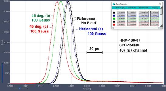
Fig. 3: IRFs
recorded for the field-free case and for configurations a , b, and c. Time
scale 20 ps / division, 200 ps for entire time axis
Similar measurements were performed on a bh
PMCS-150 detector. The field configurations were 90 degree horizontal, 90
degree vertical, and +45 degrees, see Fig. 4. Due to the smaller size of the PMCS
module, the magnet comes closer to the detector. The field strength in the axis
of the detector was therefore 150 Gauss, i.e. slightly higher than for the HPM module.
The results are shown in Fig. 4. The no field IRF and the two 90-degree IRFs
are indistinguishable. The IRF widths are about 97 ps FWHM. The 45-degree
IRF is shifted by 9.7 ps toward later times, and the FWHM is increased to
109 ps.
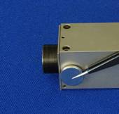
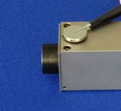
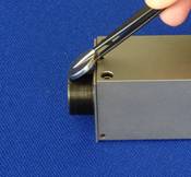
Fig. 4: Magnetic-field
test configurations for the PMC-150 detector. Field direction from detector
axis: Left (a) 90 deg horizontal, middle (b) 90 degree vertical, right (c) +45
degree vertical
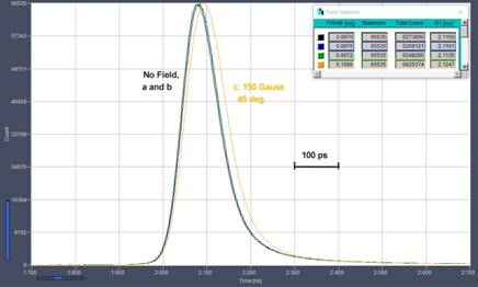
Fig. 5:
Magnetic-field dependence of IRF of PMCS-150 detector. Time scale 100 ps /
div, entire time axis is 1 ns. Note different time scale compared to Fig. 3
Discussion of the Results
The IRF shifts found in our experiments
were surprisingly small. The shift observed for the HPM (see Fig. 3) may look
large in comparison to the IRF width. However, it is only 14.4 ps, which
is on the order of the timing instability of medium-resolution TCSPC devices.
The small size of the shift is even more surprising, as the detector does not
incorporate any magnetic shielding. The explanation is the high acceleration
voltage of 8000 V, which results in a high electrical field strength
inside the hybrid-detector tube [3]. It is also plausible that the shift is
largest for the 45-degree configurations. In these cases, the strongest
magnetic field is in the vicinity of the cathode, where the velocity of the
photoelectrons is lowest.
The small size of the effect of the
magnetic field on the PMCS is similarly surprising. The detector contains a Hamamatsu
H11901 photosensor module [4], which is based on a TO9 miniature PMT. Different
than for the HPM, the acceleration voltages between the cathode and the first
dynode and between the dynodes are on the order of only 100 V. The explanation
of the small influence of the magnetic field is the small size of the detector.
The cathode-dynode distance and the interdynode distances are about 1 mm.
This results in relatively high electrical-field strengths, and in short
electron trajectories. Moreover, the H11901 modules incorporate magnetic
shielding. The only way the magnetic field can get into the tube is via the
cathode window. This is supported by the fact that the largest variation in the
IRF was found for the 45-degree configuration.
References
1. The bh TCSPC Handbook, 8th ed., www.becker-hickl.com
2. Sub-20ps IRF Width from Hybrid Detectors and MCP-PMTs. Application
note, www.becker-hickl.com
3. R10467 Series high speed compact HPD, www.hamamatsu.com
4. H11900 / H11901 Series photosensor modules, www.hamamatsu.com