Multiphoton FLIM with the Leica HyD RLD Detectors
Wolfgang
Becker, Becker & Hickl GmbH
Leica have
recently introduced hybrid detectors for the non-descanned (RLD) ports of their
SP5 and SP8 multiphoton laser scanning microscopes. We have tested these detectors
for FLIM with the bh TCSPC modules. We describe the TCSPC parameter setup and
operating conditions for the detectors, and demonstrate the performance for
typical samples.
Leica have recently introduced hybrid detector
modules for the non-descanned ports of the multiphoton versions of their SP5
and SP8 laser scanning microscopes. The modules have outputs that deliver the
single-photon pulses of the detectors to an external photon counting system. The
detector modules have two channels detecting in different wavelength intervals.
The detection intervals are selected by a standard microscope beamsplitter
filter cube. The detector module attached to an SP5 MP microscope is shown in Fig.
1, left, the output connectors in Fig. 1, right. We have tested the HyD
detector the with bh Simple-Tau TCSPC FLIM systems, see Fig. 2.
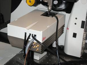
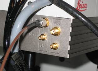
Fig. 1: Left: Leica HyD RLD dual-channel detector module at non-descanned
port of SP5 MP microscope. Right: FLIM outputs of the detector.
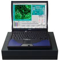
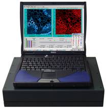
Fig. 2: bh
Simple-Tau system. Single-channel system (left) and dual-channel system (right).
The systems contain one SPC‑830 or one or two SPC‑150 TCSPC modules.
The FLIM outputs of the HyD detector were
connected directly into the CFD inputs of the TCSPC modules. For dual-channel
TCSPC systems, such as the Simple Tau 152, the two outputs of the HyD module
were connected to separate TCSPC channels. For single-channel TCSPC systems,
such as the Simple-Tau 830 or 150, the output of detector channel one was connected
to the CFD input. The SYNC (timing reference signal) was obtained from the
synchronisation output of the Ti:Sa laser, the scan clock signals were derived
from the clock breakout box of the SP5 via the standard bh scan clock cable for
the SP5. Please see [1] and [2] for details.
System Parameter Setup
CFD Threshold
The amplitude of the single-photon pulses
from the HyD detectors is about 200 mV, the polarity is negative. The
signals from the detector outputs contain about 50 mV of noise. It is thus
important that the CFD threshold of the SPC modules be set more negative than
50 mV. We found -100 mV to -200 mV appropriate to both suppress
the noise and reliably trigger on the single-photon pulses. Please see Fig. 3.
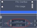
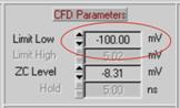
Fig. 3: General behaviour of the count rate versus CFD threshold (left, no
light on the detector), and CFD threshold in the main panel (middle) and in the
system parameters of the SPCM software (right).
Please note that the Gain of the HyD
detector in the Leica software has no influence on the effective gain of the
detector itself, and no influence on the amplitude of the single-photon pulses.
The setting is thus irrelevant for FLIM.
Scan Control Parameters
Different than other LSMs, the SP5 uses a sinusoidal
scan. The nonlinearity of the scan is compensated by a non-equidistant pixel
clock. The pixel clock periods are shorter in the centre and longer at the
outer parts of the line, see Fig. 4, left. The distance along the line then
becomes a linear function over the pixel clock periods. Only if the FLIM system
works with the pixel clock from the microscope it obtains a linearized X
coordinate. This is no problem for the bh FLIM systems: They work routinely
with external pixel clocks. The pixel clock source in the SPCM software must be
set to external, Fig. 4, right. The scan parameters allow the user to define
binning of pixels and lines, to shift the recorded part of the scan in X and Y,
or to select between two different frame clock sources. The scan parameters
shown in Fig. 4 were chosen to obtain a FLIM image of the same pixel number as
the SP5 scan. Please see [1] for details.
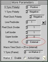
Fig. 4: Left: Sinusoidal scan and linearization by non-equidistant pixel
clock. Right: Scan parameter setup in the SPCM software. The pixel clock must
be external to compensate for the nonlinearity of the sinusoidal scan.
MP laser control in the SP5
The MP laser control parameters of the
Leica software have significant influence on the image recording. The
parameters, especially the Offset, must be set that the laser beam is turned
on during the active part of the line period, and turned off during the rest of
the line, see Fig. 5, left and middle. It seems that inappropriate settings can
effectively reverse the laser-on and laser-off phases. In less severe cases,
the microscope (and the FLIM system) may still acquire images, but the laser
intensity may be higher in the flyback phase than in the active part of the
scan, see Fig. 5, right. This can cause unnecessary load on the sample, massively
increased photobleaching, and early bus saturation in the FLIM system.
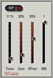
Fig. 5: Left: MP laser adjust panel in Leica Microscope Software. Middle:
Laser power versus line period. Right: Laser power for inappropriately set MP
laser adjust parameters.
Results
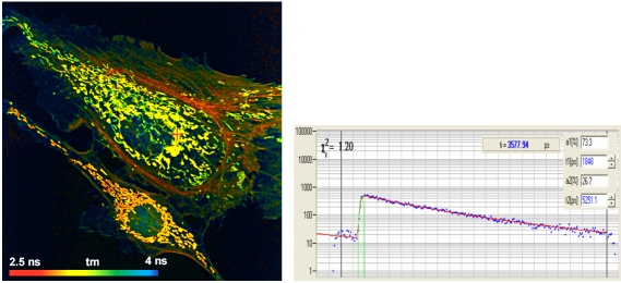
Fig. 6 shows a lifetime image of a BPAE
Cell labelled with Alexa 488 Phalloidin and Mito Tracker Red. The excitation
wavelength was 860 nm. The laser wavelength was blocked by the standard
680 nm short-pass filter. No bandpass filter was used. The FLIM data were
recorded in the FIFO Imaging mode, with 512 x 512 pixels and 256
time channels. The usual precautions against room light pickup were used: All
room lights were turned off, the back of the sample was covered by black paper,
and the microscope was wrapped in black cloth. The decay data were fitted by a
double-exponential decay model. A fluorescence decay curve at the position
marked with the red cross is shown on the right. The decay data are clean,
without any trace of reflections or laser leakage. Due to the long fluorescence
lifetime there is some residual fluorescence from the previous laser pulse
periods. This signal component is, however, correctly fitted by the incomplete
decay model of the bh SPCImage data analysis software [1, 3].
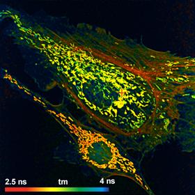

Fig. 6: Left: Lifetime image of a BPAE cell, labelled with Alexa 488 and
Mito Tracker red. Amplitude-weighted lifetime of double-exponential decay. Right:
Fluorescence decay curve at position marked with red cross. bh SPC‑830
TCSPC module, image format 512 x 512 pixels, 256 time channels.
Analysis by bh SPCImage, double exponential decay model with incomplete decay
option.
Autofluorescence images of pig skin are
shown in Fig. 7. The FLIM data format is 512 x512 pixels, 256 time
channels. The excitation wavelength was 800 nm. No bandpass filter was
inserted, only the SP 680 laser blocking filter was used. Thus, the FLIM
data contain both fluorescence and SHG components. The image on the left shows
the intensity-weighted lifetime of a triple-exponential fit, the image on the
right the relative intensity fraction in the ultra-fast (SHG) component.
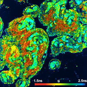
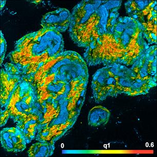
Fig. 7: FLIM of Pig skin, image format 512 x512 pixels, 256 time
channels. Left: Lifetime image, intensity-weighted lifetime of
triple-exponential decay model. Right: Relative intensity of SHG component in
total signal. bh SPC-830 TCSPC module, Analysis by bh SPC Image.
Instrument Response Function
We did not explicitly record the temporal
IRF of the HyD detector. It can, however, be estimated from the SHG components
in the FLIM images shown in Fig. 7. Fig. 8, left, shows decay functions in a
region dominated by SHG. The full-width at half maximum is about 130 ps, same
as for the bh HPM‑100-40 detectors [1, 4]. No intensity-dependent timing
shift was observed, see Fig. 8, right.

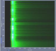
Fig. 8: IRF data extracted from the FLIM
data in Fig. 7. Left: Decay functions in a region dominated by SHG. The Width
of the curves is about 130 ps. Right: Decay functions over a vertical
stripe of Fig. 7 displayed in colour-intensity mode. The distance between the
vertical lines is 100 ps. No timing shift depending on the intensity is
observed.
Sensitivity
Sensitivity comparison of detectors in
laser scanning microscopy is notoriously difficult. It would require
measurements of the same area of a test sample in exactly the same focal plane
with the same laser power for different detectors. We therefore did not attempt
a direct comparison. However, the count rates obtained for a given sample and
given laser power were about the same as they are observed with bh HPM‑100-40
hybrid detectors on other SP5 microscopes.
Summary
The HyD RLD detectors of the Leica SP5 and
SP8 multiphoton microscopes are fully compatible with the bh TCSPC FLIM
systems. We found an IRF width of about 130 ps. The decay curves recorded
with the HyD detectors were clean, without bumps, ripple or reflections. The
detectors should be used with a CFD threshold of -100 mV to -200 mV.
The pixel clock of the TCSPC system must be external to linearise the x
coordinate of the scan. Moreover, we recommend to carefully adjust the MP laser
control parameters in the Leica microscope software.
Acknowledgement
We thank Dr. J.
Requejo-Isidro, Biophotonics Lab, Unidad de Biofisica (CSIC-UPV/EHU), Leioa
(Vizcaya), Spain, for devoting his microscope, his FLIM
system, and his time to the tests.
References
1.
W. Becker, The bh TCSPC handbook. 5th edition. Becker
& Hickl GmbH (2012), available on www.becker-hickl.com, please contact bh for printed
copies
2.
Becker & Hickl GmbH, NDD FLIM Systems for
Leica SP2 MP and SP5 MP Multiphoton Microscopes. Application note, available on
www.becker-hickl.com.
3.
Becker & Hickl GmbH, SPCImage Data
Analysis Software for Fluorescence Lifetime Imaging Microscopy, available on
www.becker-hickl.com
4.
Becker, W., Su, B., Weisshart, K. & Holub,
O. (2011) FLIM and FCS Detection in Laser-Scanning Microscopes: Increased
Efficiency by GaAsP Hybrid Detectors. Micr. Res. Tech. 74, 804-811