DCS-120 Confocal FLIM System with Wideband
Beamsplitter
Wolfgang
Becker, Becker & Hickl GmbH
The use of a wide range of excitation
wavelengths in a confocal laser scanning system leads to a number of design
problems. The most critical one is connected to the main dichroic beamsplitter
that separates to fluorescence signals from the excitation beam. For use with
several lasers the beamsplitter must either be switchable or tuneable, or a
multiband dichroic must be used. The result is either alignment instability, or
spectral gaps in the fluorescence detection channels. We developed a version of
the DCS-120 confocal FLIM scanner that bypasses most of these problems by using
a wideband beamsplitter. The design allows the user to switch lasers without
compromising alignment stability. The sensitivity of the system is sufficient
to record autofluorescence images of single cells.
Motivation of Using Wideband Systems
There is a wide variety of fluorescence
markers used in laser scanning microscopy. The fluorescent proteins alone span
over an excitation wavelength range of almost 200 nm [4, 6]. Moreover, there is increasing interest
in using near-infrared dyes, with absorption maxima up to 800 nm [5, 9].
Users of laser scanning microscopes therefore want their system to be ready for
working with a wide range of different laser wavelengths. Increasing the number
of excitation wavelengths is often considered easy: Add more lasers to the
system, make lasers interchangeable, or just use a tuneable laser.
Unfortunately the task is not as simple as
it may appear. The reason is the main dichroic beamsplitter of the scanning
system. The beamsplitter is designed to reflect the laser beams down the beam
path of the microscope, and transmit the fluorescence returned from the sample
to the detectors, see Fig. 1.
Fig. 1: Basic function of the main dichroic beamsplitter in a confocal
scanning system
To work with several lasers of different
wavelength the beamsplitter either must be replaced when the laser is changed,
or the beamsplitter must be designed to reflect several lasers. Both approaches
have advantages and disadvantages.
Switching the beamsplitters (i.e. by
placing several dichroics on a wheel) requires extraordinary mechanical
precision. If the direction of the beam changes only by a few arc seconds the
laser spot in the sample moves, and the fluorescence beam is no longer focused
into the pinhole. That means in practice that there must be some kind of
automatic re-alignment that corrects for angle variations between the different
dichroics. There is also a second disadvantage: Fast multiplexing of lasers of
different wavelengths within pixels, lines, or frames is impossible.
Another way of dealing with several wavelengths
is to use a main dichroic beamsplitter that has several reflection and
transmission bands. The standard versions of the bh DCS-120 confocal scanner
use this design [1, 2]. It delivers high efficiency and excellent mechanical
stability, and allows lasers to be multiplexed at high rate. The problem of the
multi-band dichroic is, however, that it can be made only for a very limited
number of laser wavelengths. Fluorescence cannot be transmitted within the
laser reflection bands, and the reflection bands cannot be made narrower than
about 10 nm. This is especially the case for ps diode lasers diode lasers
that can vary in wavelength and have several nm of spectral bandwidth.
Moreover, a reasonable manufacturing tolerance for the dichroic must be left.
That means in practice that the dichroic can only be made for two or three laser
wavelengths which are reasonably spaced from each other.
There are other solutions, like
acousto-optical beamsplitters (AOBS) or variable-wavelength dichroics. However,
these have other problems: An AOBS has narrow bandwidth and less-than ideal
sideband suppression. Moreover, its common use is prevented by patent issues. A
variable-wavelength dichroic has to be moved when the wavelength is changed,
which again causes stability problems and makes fast laser multiplexing
impossible.
The easiest way to avoid these problems is
to go back to Minskys original design [7, 8] and use a wideband beamsplitter, i.e.
a partially reflective mirror, see Fig. 2.
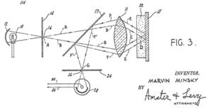
Fig. 2: Minskys design with partially reflecting mirror as a main
beamsplitter and implementation in DCS-120
At first glance, a wideband beamsplitter
may appear a very poor design: A considerable part of the emission and the
excitation light would be lost. A somewhat closer look, however, shows that Minskys
approach is not so poor after all: The vast majority of TCSPC FLIM experiments
is performed at less than 10% of the available laser power. Under these
conditions, a loss in excitation power at the beamsplitter can easily be
compensated for by increasing the laser power at the input of the scanner.
The loss in detection efficiency is more
serious: Any loss in efficiency results either in a decrease in fluorescence
lifetime accuracy, or in an increase in acquisition time. However, also here
practice teaches different: Consider a 60/40 beamsplitter, with 60% transmission
for the fluorescence. The factor of 0.6 in efficiency is the same as the ratio in
collection efficiency between an NA=1.0 water immersion lens and an NA=1.3 oil
immersion lens. In contrast to beamsplitter efficiency, the dependence of the
collection efficiency on the NA is commonly ignored. No one would hesitate to
use the water immersion lens to obtain better images of live cells, no matter
of what the collection efficiency is. It therefore appears reasonable to
sacrifice 40% collection efficiency for obtaining more flexibility in laser
wavelengths.
The options for using wideband
beamsplitters have also improved by the introduction of new detectors: Hybrid
detectors are far more efficient than previously used PMTs. The increase in
efficiency is not only due to a better cathode quantum efficiency but also to
the absence of afterpulsing background [1, 3]. The result is that a given
accuracy in fluorescence lifetime is obtained at a substantially lower sample
emission rate. A scanning system with wideband beamsplitter and a hybrid
detector therefore delivers at least the efficiency as a system with a dichroic
beamsplitter and a conventional PMT.
Technical Issues
Using a wideband beamsplitter in a confocal
scanning system solves the problem of alignment stability for different laser
wavelengths. However, this does not mean that that there are no pitfalls. The
technical issues associated with wideband systems are discussed in the section
below.
Wideband Emission of Diode Lasers
All laser diodes are more or less plagued
by a spectrally broad background of wideband emission. The background results
from luminescence of the semiconductor material. It is excited both by the
laser radiation and by late recombination of electron-hole pairs. The background
emission is orders of magnitude weaker than the laser emission but shows up clearly
when the laser wavelength is blocked by a filter. Typical spectra for the bh
BDL-SMC lasers (with Nichia laser diodes) are shown in Fig. 3.
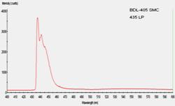
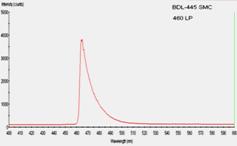
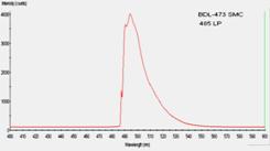
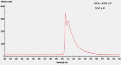
Fig. 3: Spectra of wideband emission from picosecond diode lasers. The
laser wavelength was blocked by long-pass filters as indicated in the diagrams.
Wavelength scale from 400 to 600 nm.
The spectra were recorded in the picosecond
mode with the laser wavelength blocked by long-pass filters. Filter wavelengths
are indicated in the diagrams. Please note that some ripple may be induced in
the spectra by the filter characteristics. Typical waveforms of the background
are shown in Fig. 4. The waveforms contain a background from long-lifetime
luminescence, and short-decay components. The ripple on the curves is real and
probably comes from ringing of the diode reverse voltage after the driving
pulse.
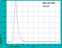
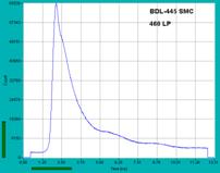
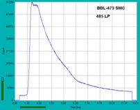
Fig. 4: Waveforms of wideband emission from 405nm, 445nm, and 473nm ps
diode lasers. Laser wavelength blocked by filters, as indicated in the diagrams
For a confocal scanner that uses a dichroic
beamsplitter spectral background from the laser is not normally a problem. The
main dichroic beamsplitter acts as a bandpass or low-pass filter for the laser
and thus suppresses the background. However, there is no such background
suppression by a wideband beamsplitter. Systems with wideband beamsplitters
must therefore be operated with filters in the laser beam path.
There are versions of the BDL‑SMC
lasers that have a cleaning filter integrated. For lasers without integrated
filters a cleaning filter can be inserted in the collimator barrels of the
fibre couplers. Suitable filters and filter holders are available from bh.
Variation of Laser Wavelength, Spectral Width
The emission wavelength of different laser diodes
of the same wavelength type can vary considerably. Variations up to 10 nm
are not unusual. Moreover, the spectral width is larger in the picosecond mode
and can reach 10 nm in some cases, see Fig. 5, right.
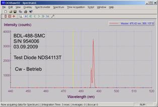
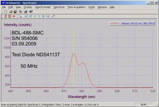
Fig. 5: Left: Optical spectrum in CW mode, power 30 mW. Right:
Optical spectrum in picosecond mode, 50 MHz, average power 0.8 mW.
For one and the same diode, there can also
be a spectral shift between CW operation and picosecond operation. For most
diodes this shift is only a few nm. However, for the Nichia 488 nm diodes
it can be almost 10 nm, see Fig. 5. Both diode-specific variations and
shift between CW and ps operation have to taken into consideration when
cleaning filters are specified.
Emission Path Filters
In a system with a dichroic beamsplitter it
is normally sufficient to use an emission filter that reliably blocks the laser
wavelength. For wideband systems this is not necessarily sufficient. For
reasons explained above, the cleaning filter in the laser beam path has to
leave room for laser wavelength tolerance, spectral width, and spectral shift. In
practice, the cleaning filter transmission range must be about 20 nm wide.
This has consequences to the selection of the filters in the detection beam
path: The detection filters of a wideband system must be selected to block not
only the laser wavelength, but the whole transmission range of the cleaning
filter.
Filter issues are especially important for
samples of low fluorescence yield and samples with strong scattering. A filter
combination that delivers acceptable results for clear samples (see Fig. 8 and Fig.
9) does not necessarily work for thick tissue samples or other highly
scattering objects. Please note that laser background has a waveform very
similar to the fluorescence decay in the sample (see Fig. 4). Laser spectral
background scattered back from the sample is therefore hard to identify. The
only way of avoiding contamination with laser background is correct selection
of filters.
Optical Reflections
Optical reflections from glass surfaces are
much more troublesome in wideband systems than in systems with dichroic
beamsplitters. Of course, in correctly designed scanner optics reflected laser
light should not be focused into the pinholes. However, if the pinholes are
opened wide reflected light may leak into the detectors. Reflected laser
background can be identified by the fact that it arrives earlier than the
fluorescence signal from the sample. Moreover, it is also detected when the
sample is removed.
Fig. 6 shows an example. The data were
recorded with a BDL-473SMC laser and a 475 ± 25 nm cleaning
filter. The image shown left was recorded through a 485 nm long pass
filter. This filter efficiently blocks the 473 m laser wavelength, but not
the full transmission range of the cleaning filter. The waveform (shown in the
middle) shows the decay function of the reflected laser background. Please note
that the rising edge of the signal is not visible: It is outside the recording
range because the reflected signal arrives earlier than the sample fluorescence.
The image on the right was recorded with a 535 ± 25 nm bandpass filter
in the detection path. This filter has no overlap with the cleaning filter. It
removes the laser background signal entirely.
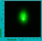
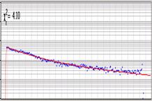
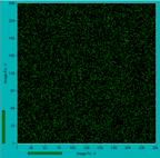
Fig. 6: Left: Laser background reflected at the scan lens, recorded with an
emission filter that blocks only the laser wavelength. Middle: Waveform of
signal, the rising edge is left of the recorded interval. Right: Non-overlapping
filtering removes the problem entirely. DCS‑120 with wideband
beamsplitter, BDL-473 SMC laser, Pinhole 5 AU.
Polarisation
Laser background signals are highly
polarised. Suppression of laser background is therefore especially important
for fluorescence anisotropy and anisotropy decay measurements.
Moreover, it should be noted that a
wideband beamsplitter is not entirely polarisation-independent. Polarisation-independent
detection is, however, essential in order to cancel the influence of the anisotropy
decay on the recorded decay functions. With a dichroic beamsplitter the
anisotropy decay is cancelled by simply using high-NA objective lenses [1].
This is not exactly the case for a wideband beam splitter. Polarisation on a
wideband beamsplitter is on the order of 10%. We believe that the effect of the
anisotropy decay is small enough to have no noticeable influence on the
fluorescence decay functions recorded. Detailed tests still have to be done.
Swapping Lasers
The intention of using a wideband
beamsplitter is the ability to connect a large number of different lasers to
the system. The DCS‑120 uses precision fibre connectors of the
Point-Source type both at the laser and at the scanner side, see Fig. 7, left
and right. The reproducibility of these connectors is so good that fibres can
be swapped virtually without re-alignment. If necessary, fine confocal alignment
can be done by the alignment screws of the fibre manipulators at the scanner
input [2].
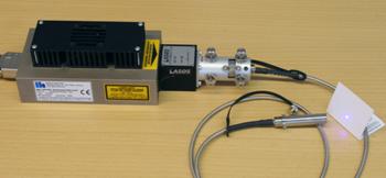
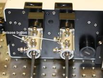
Fig. 7: Fibre coupling system used for BDL-SMC lasers and DCS-120 scanner
A few pitfalls do, however, exist also
here. Single-mode fibres are designed for a single laser wavelength, or for a
certain wavelength range. Moreover, unless lasers with integrated filters are
used cleaning filters must be inserted in the collimator barrels of the fibres.
For these reasons, fibres usually cannot be swapped at the laser side.
Swapping fibres at the scanner side bears
another problem: The collimators at the fibre outputs must produce a perfectly
collimated beam. Poor collimation is no problem for a permanently attached
fibre - it can be corrected for by the divergence corrector of the DCS-120
scanner. However, if fibres are swapped the collimation state for different
fibres must be identical. If the collimation is wrong the laser would no longer
be focused into the same focal plane the pinhole is looking at. The result
would be substantial loss in intensity, and poor optical resolution. Therefore,
a DCS system that allows for swapping laser fibres must use especially specified
fibres of similar collimation state.
Results
Fig. 8 and Fig. 9 show that the DSC-120
with a wideband beamsplitter delivers lifetime images of good quality. Fig. 3
shows a convallaria sample, excited with the 405 nm (left) and with the
473 nm (right) BDL-SMC laser. There is no intensity problem for this
sample, count rates of several MHz are obtained at a fraction of the available
laser power.
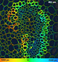
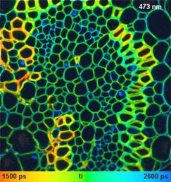
Fig. 8: Lifetime images of a Convallaria sample. DCS-120 system with
wideband beamsplitter. Left: Excitation 405 nm, detection from 435 to
500 nm. Right: Excitation 473 nm, detection from 500 to 550 nm.
Wideband beamsplitter 40/60, Nikon NA=1.3 oil immersion lens. Image format
512 x 512 pixels, 256 time channels.
Fig. 9 shows an autofluorescence image of a
human epithelium cell. The 405 nm laser was used at a power of about
0.6 mW, where it still delivers near-gaussian pulse shape. The laser
attenuator at the input of the DCS‑120 was fully opened. Under these
conditions, even standard PMC‑100‑20 PMT modules delivered a count
rate on the order of 50,000 to 80,000 counts per second. The count rate with
the more sensitive hybrid detectors is about 300,000 counts per second.
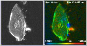
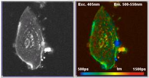
Fig. 9: Autofluorescence images of human epithelium cell, excitation with
BDL-405SMC 405 nm ps diode laser. Left: Emission wavelength range
430 to 500 nm. Right: Emission wavelength range 500
to 550 nm. Intensity images and lifetime images. DCS-120 system with
wideband beamsplitter, pinholes 1.5 AU, PMC‑100‑20 detectors.
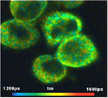
An image recorded at 640 nm excitation
wavelength is shown in Fig. 10. It shows cells stained with the dye Odyssys 680.
An HPM‑100-40 hybrid detector was used, the detection wavelength was 680 to
720 nm. Interestingly, the dye displays a slightly double-exponential
decay function, and lifetime variations on the order of 200 ps. Whether
the inhomomogeneity is caused by variation in the binding or by variation of other
cell parameters is not known.
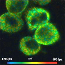
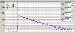
Fig. 10: Cells stained with red-absorbing dye, excitation with
BDL-640 SMC (640 nm), detection from 680 to 720 nm. Right:
Fluorescence decay function in selected spot of the cells.
Conclusions
The use of a wideband beamsplitter is a way
to operate the bh DCS‑120 confocal scanning FLIM system with more than
the standard two excitation wavelengths. Different lasers can be connected to
the DCS-120 by simply swapping the single-mode fibres at the input of the scan
head. A few precautions are, however, recommended. Laser delivery fibres of
tightly tolerated collimation state should be used, and cleaning filters must
be inserted in the lasers or in the fibre collimators. The transmission band of
the filters in the detection path should not overlap with the transmission band
of the cleaning filters. With these precautions, high-quality FLIM results are
obtained for a wide variety of laser wavelengths.
References
1. W. Becker, The bh TCSPC handbook. Becker & Hickl GmbH, 4th
edition (2008), www.becker-hickl.com
2. Becker & Hickl GmbH, DCS-120 Confocal Scanning FLIM Systems,
user handbook. www.becker-hickl.com
3. Becker & Hickl GmbH, The HPM‑100-40 hybrid detector.
Application note, www.becker-hickl.com
4. M. Y. Berezin, S. Achilefu, Fluorescence lifetime maesurement and
biological imaging. Chem. Rev. 110(5), 2641-2684 (2010)
5. M.Y. Berezin, H. Lee, W. Akers, S. Achilefu, Near infrared dyes as
lifetime solvatochromic probes for micropolarity measurements of biological
systems. Biophys. J. 93, 2892-2899 (2007)
6. R.N. Day, F. Schaufele, Fluorescent protein tools for studying
protein dynamics in living cells: A review. J. Biomed. Opt. 13(3),
031202-1 to -6 (2008)
7. M. Minsky, US Patent 3013467, (1957)
8.
M. Minsky, Memoir on inventing the confocal
microscope, Scanning 10, 128-138 (1988)
9. S.Yazdanfar, C. Joo, C. Zhan, M.Y.
Berezin, W.J. Akers, S. Achilefu, Multiphoton microscopy with near infrared
contast agents. J. Biomed. Opt. 15(3), 030505-1 to -3 (2010)