
- Complete Confocal Laser Scanning FLIM Systems, Including Microscope and Lasers
- Confocal FLIM Upgrades for Existing Conventional Microscopes
- Excitation by two BDS-SM ps Diode Lasers
- Excitation Wavelengths from 375 nm to 640 nm
- Scanning by Fast Galvanometer Mirrors
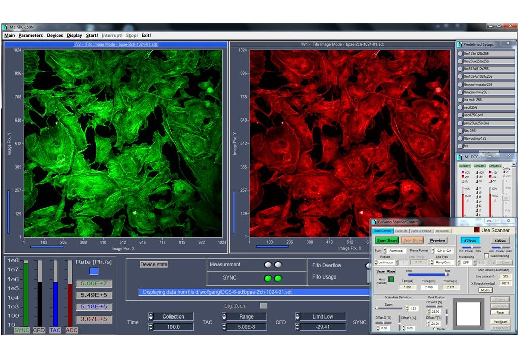
- Two Confocal Detection Channels
- Suppression of Scattering and Straylight
- Channel Separation by Dichroic or Polarising Beamsplitters
- Individually Selectable Pinholes and Filters
- Recording by bh's Multidimensional TCSPC Process
- Two Fully Parallel TCSPC FLIM Channels
- Time Channel Width Down to 405 fs
- Ultra-Fast and Ultra-Sensitive Detectors
- Unprecedented Time Resolution
- Detection of Lifetimes <25 ps
- Near-Ideal Photon Efficiency
- Excellent Lifetime Reprodicibility
- Fast Online-FLIM
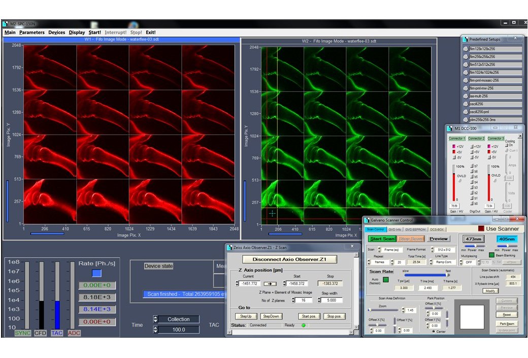
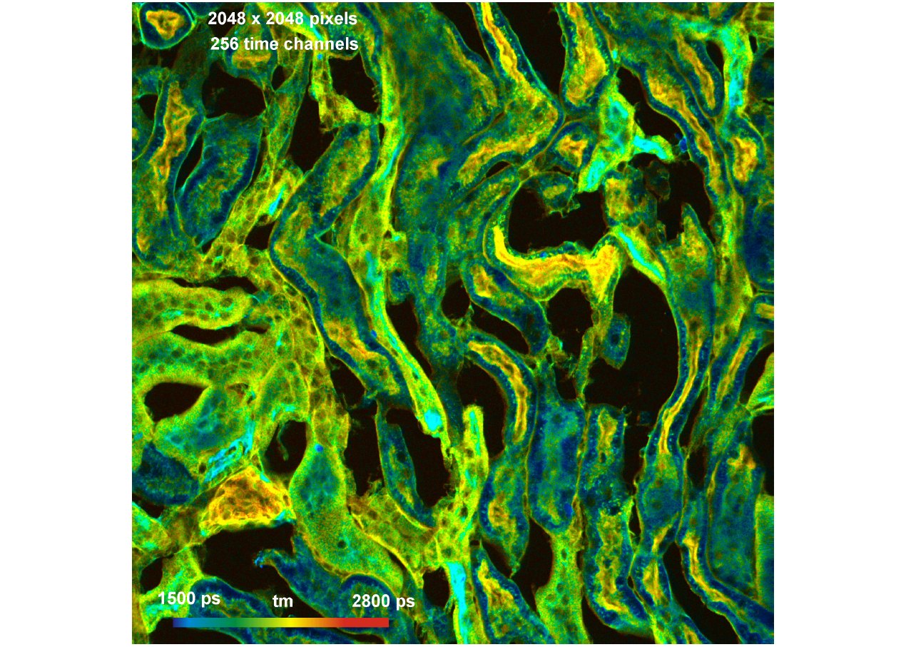
- Megapixel FLIM, 2048 x 2048 Pixels
- Precision FLIM, 4096 Time Channels
- Mosaic FLIM
- Z Stack FLIM
- Accumulation of Fast Time Series
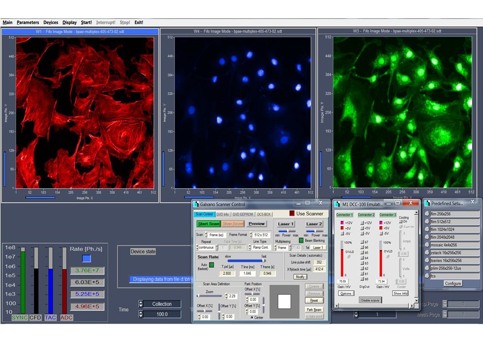
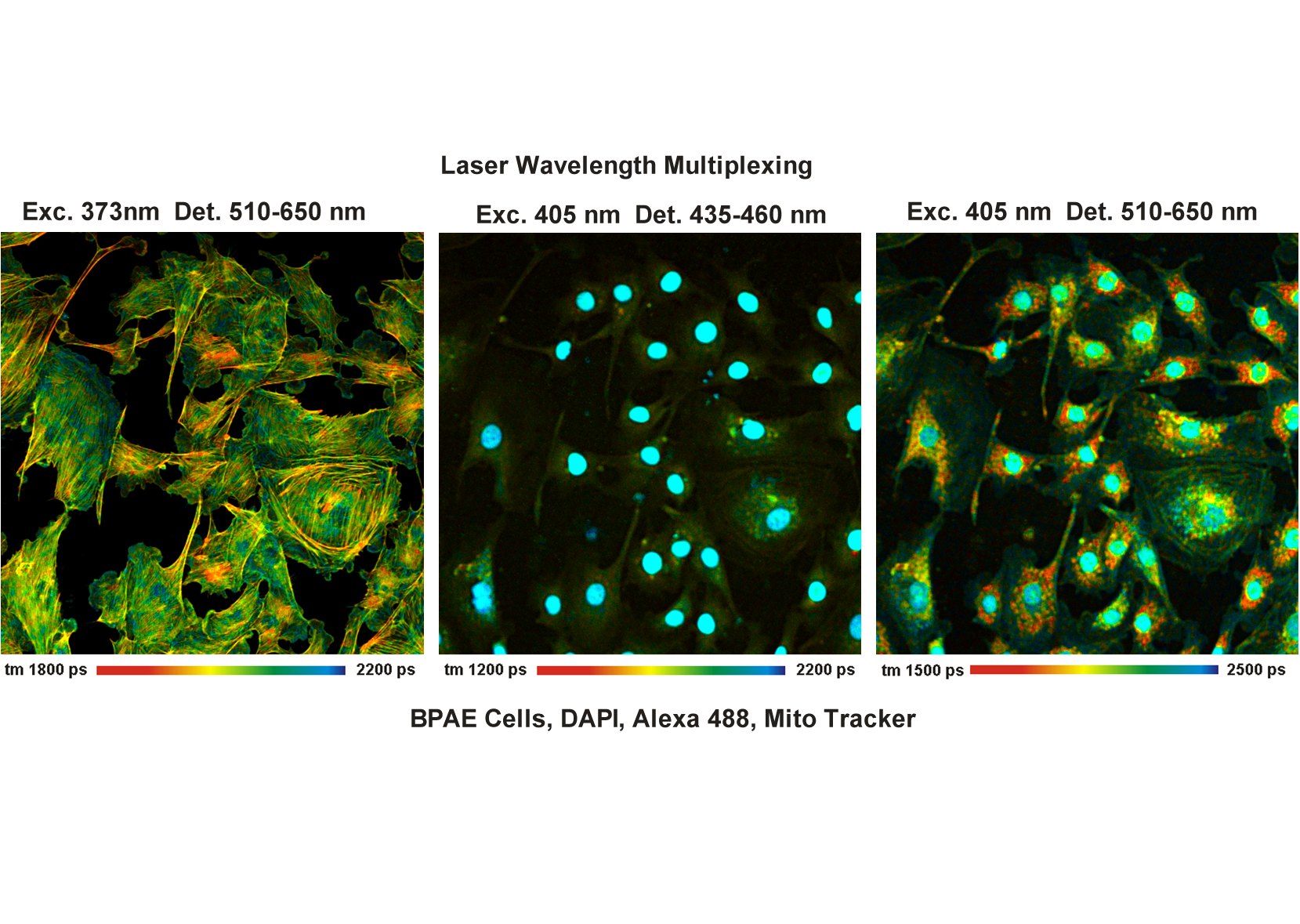
- Excitation Wavelength Multiplexing
- Multi-Wavelength FLIM
- Simultaneous FLIM/PLIM
- Integrated Motorized Sample Stage
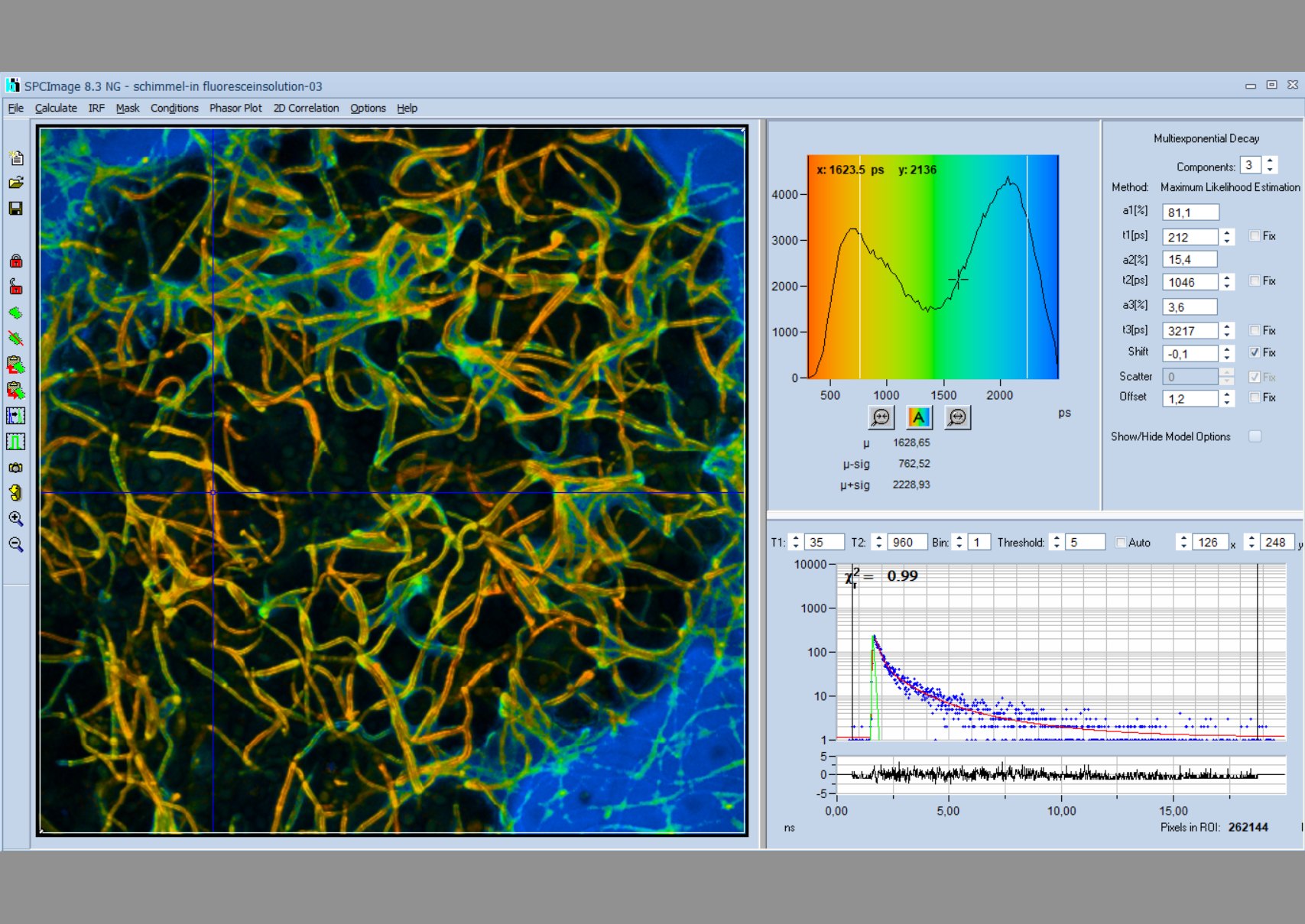
- Data Analysis by bh SPCImage NG
- Ultra-Fast Processing by GPU
- Combination of Time-Domain Analysis and Phasor Plot
- Image Segmentation by Phasor Plot or 2D Histograms
- MLE (Maximum-Likelihood Estimation) Fit of Decay Data
- Automatic IRF Modelling
- No Need to Record IRF
Description
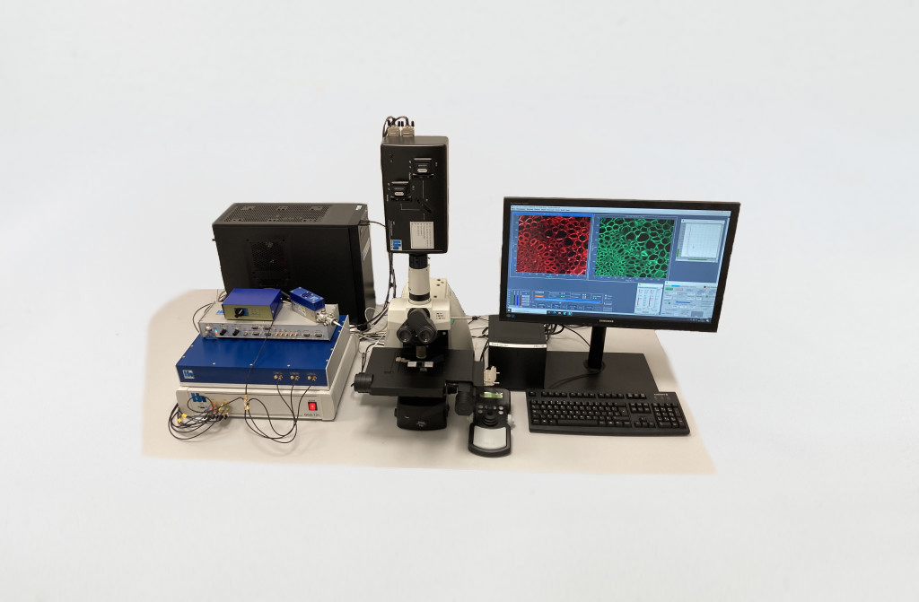
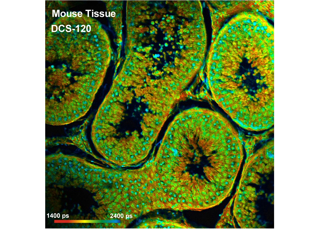
The DCS-120 confocal FLIM system uses excitation by ps diode lasers, fast scanning by galvanometer mirrors, confocal detection, and FLIM by bh’s multidimensional TCSPC technique. It records fluorescence lifetime images at unprecedented temporal resolution, unprecedented reproducibility, high spatial resolution, high sensitivity, and near-ideal photon efficiency. Fluorescence lifetimes can be detected down to 25 ps; the decay data can be resolved into 4096 time channels of down to 405 fs width. The pixel format can be increased to 2048 x 2048.
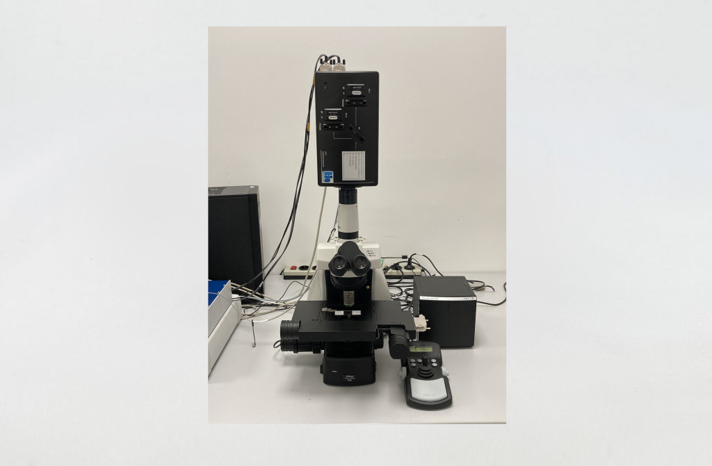
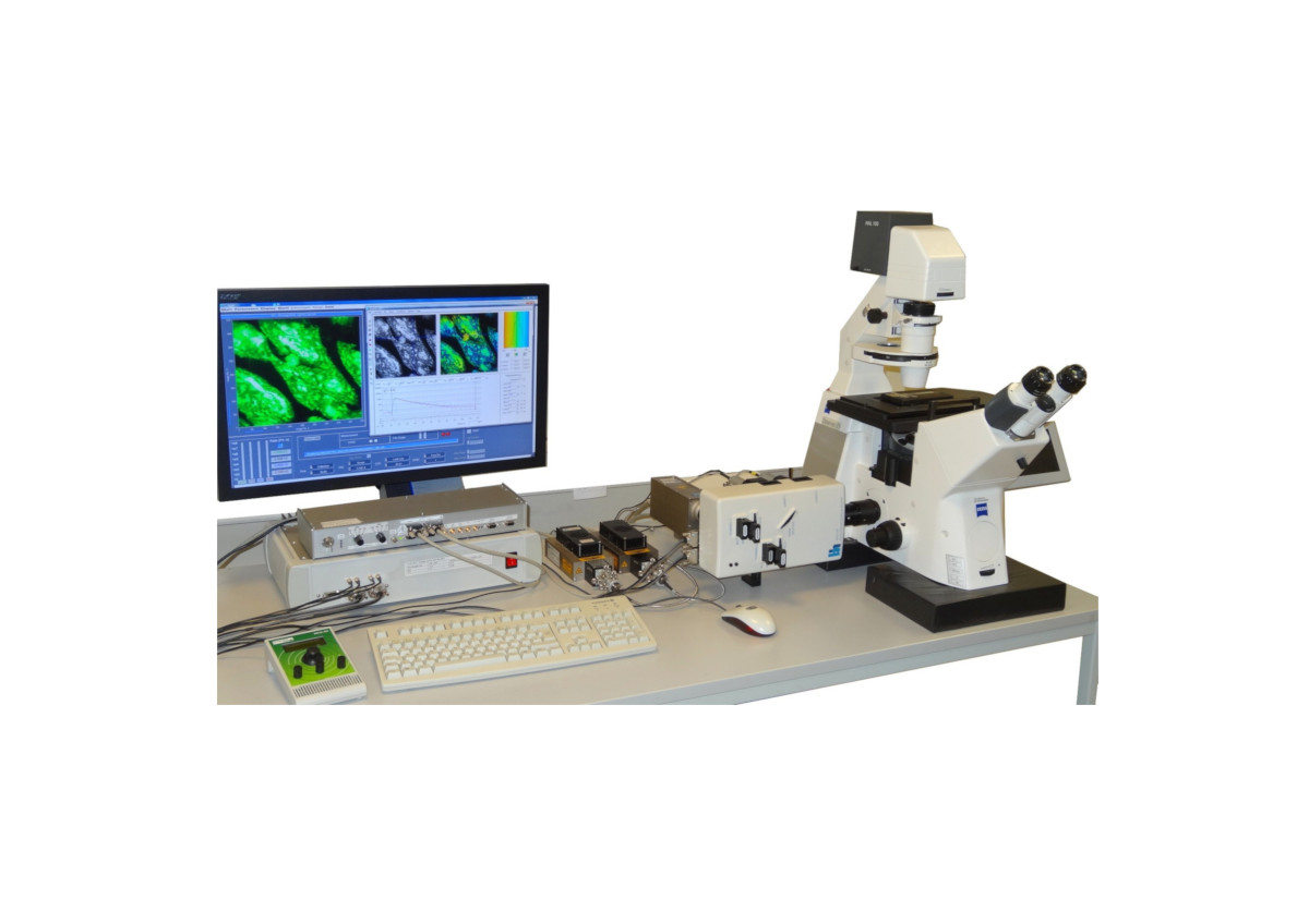
The DCS 120 system is available with inverted microscopes of Nikon, Zeiss, and Olympus. It can also be used to convert an existing conventional microscope into a fully functional confocal or multiphoton laser scanning microscope with TCSPC detection. Due to its fast beam scanning and its high sensitivity the DCS-120 system is compatible with live-cell imaging.
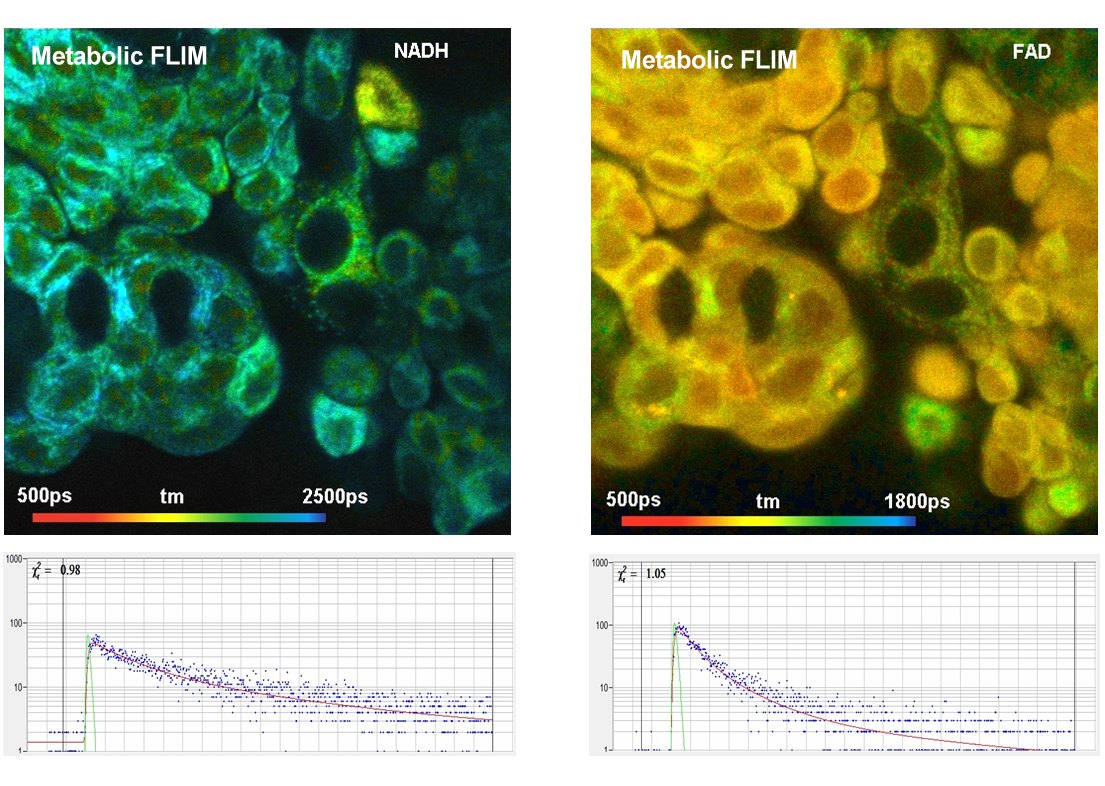
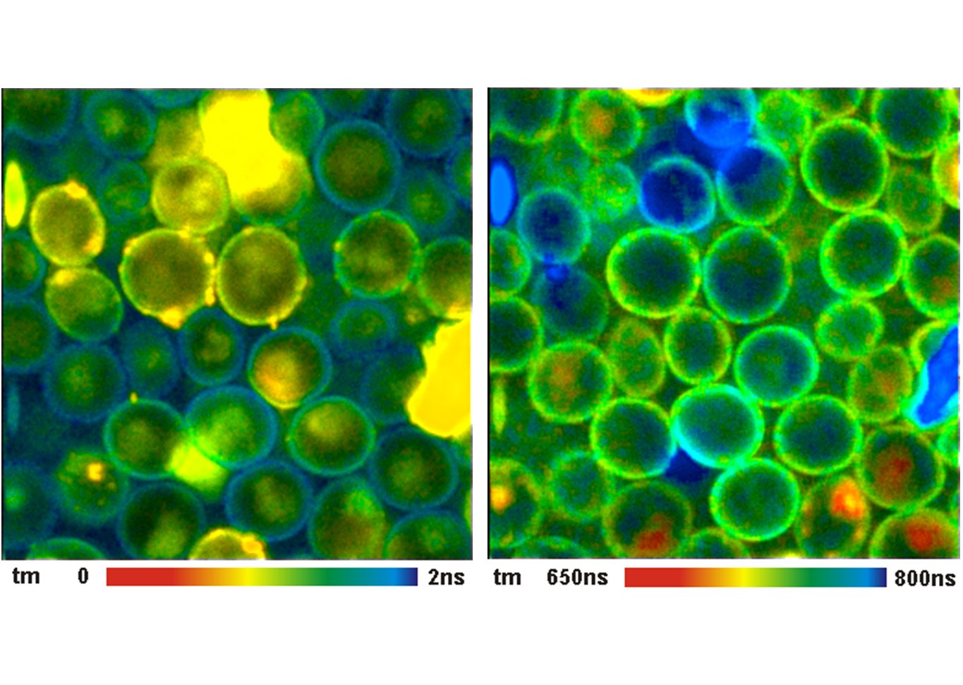
DCS-120 functions include recording of FLIM or steady-state fluorescence images simultaneously in two fully parallel wavelength channels, laser wavelength multiplexing, multi-wavelength FLIM, time-series FLIM, ultra-fast time-series recording by temporal-mosaic FLIM, spatial mosaic FLIM, Z stack FLIM, phosphorescence lifetime imaging (PLIM), fluorescence lifetime-transient scanning (FLITS) and FCS recording. Applications focus on metaboloc imaging, i.e. the use of lifetime changes by interactions of fluorophores with their molecular environment. Typical applications are ion concentration measurement, FRET experiments, metabolic imaging, imaging of fast physiological effects, and plant physiology.
Data analysis is performed by bh's new SPCImage NG FLIM analysis software. SPCImage NG is a combination of time-domain and phasor analysis. By running the calculations on a GPU (Graphics Processor Unit) the results are available within seconds. Other features are the availability of image segmentation via the phasor plot or via 2D time-domain histograms, and automatic modelling of the system IRF. Repeated recalibration by recording the actual IRF is thus unnecessary.
Specifications
Selected Specifications
Principle: Scanning by fast galvanometers scanner, confocal detection, and TCSPC FLIM by bh's Multi-dimensional TCSPC technique
Excitation: Picosecond diode lasers
Scan Rate: Down to about one microsecond per pixel
Buildup of Lifetime Images: Distribution of photons over arrival times and scan coordinates
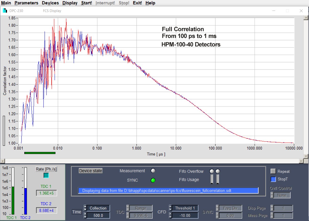
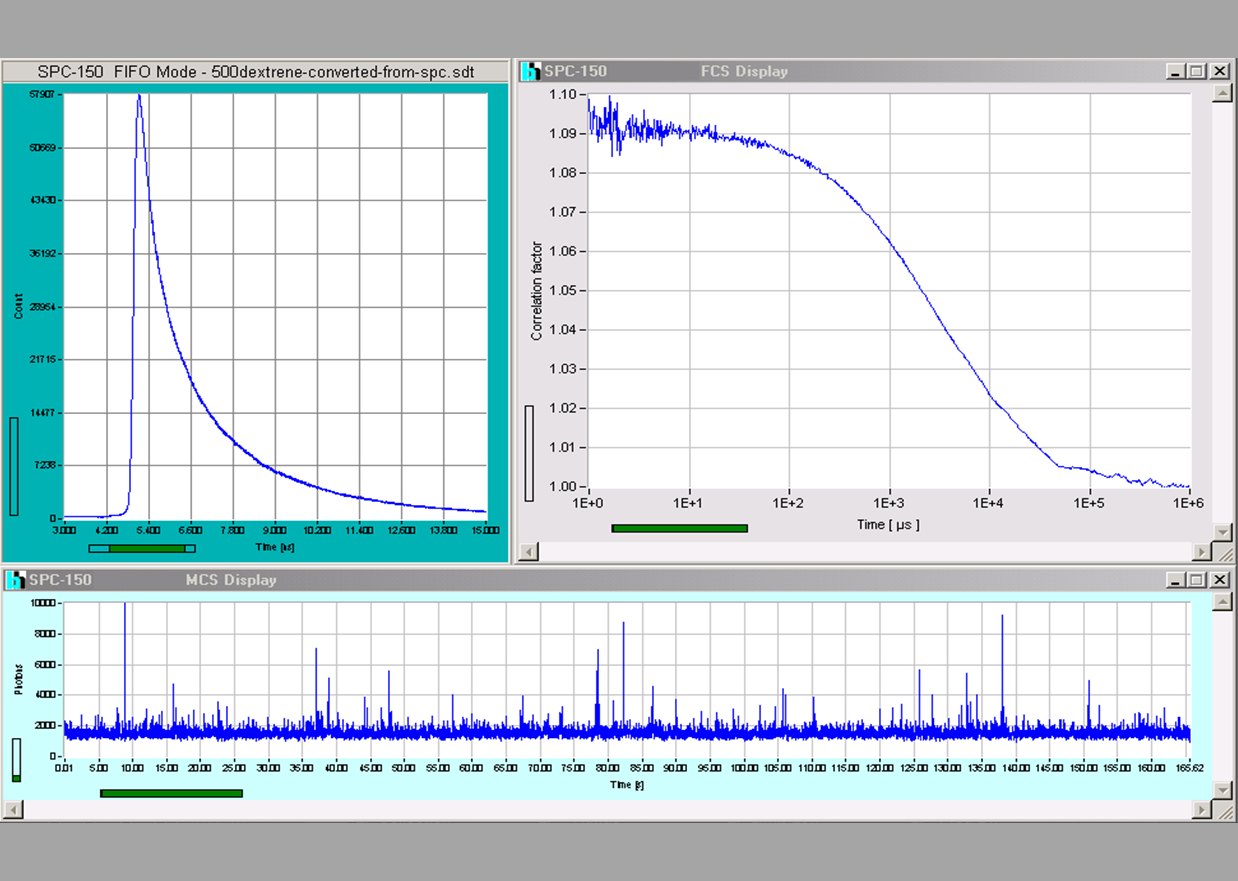
Buildup of Fluorescence Correlation Data: Correlation of absolute photon times
General Operation Modes: FLIM in two spectral or polarisation channels, Multi-wavelength FLIM,
Time-series FLIM, Z-Stack FLIM, Mosaic FLIM, x,y, z, temporal, Excitation-wavelength multiplexed FLIM, FLITS (fluorescence lifetime-transient scanning), PLIM (phosphorescence lifetime imaging) simultaneously with FLIM, FCS, cross FCS, gated FCS, single-point fluorescence decay recording, single-point phosphorescence decay recording
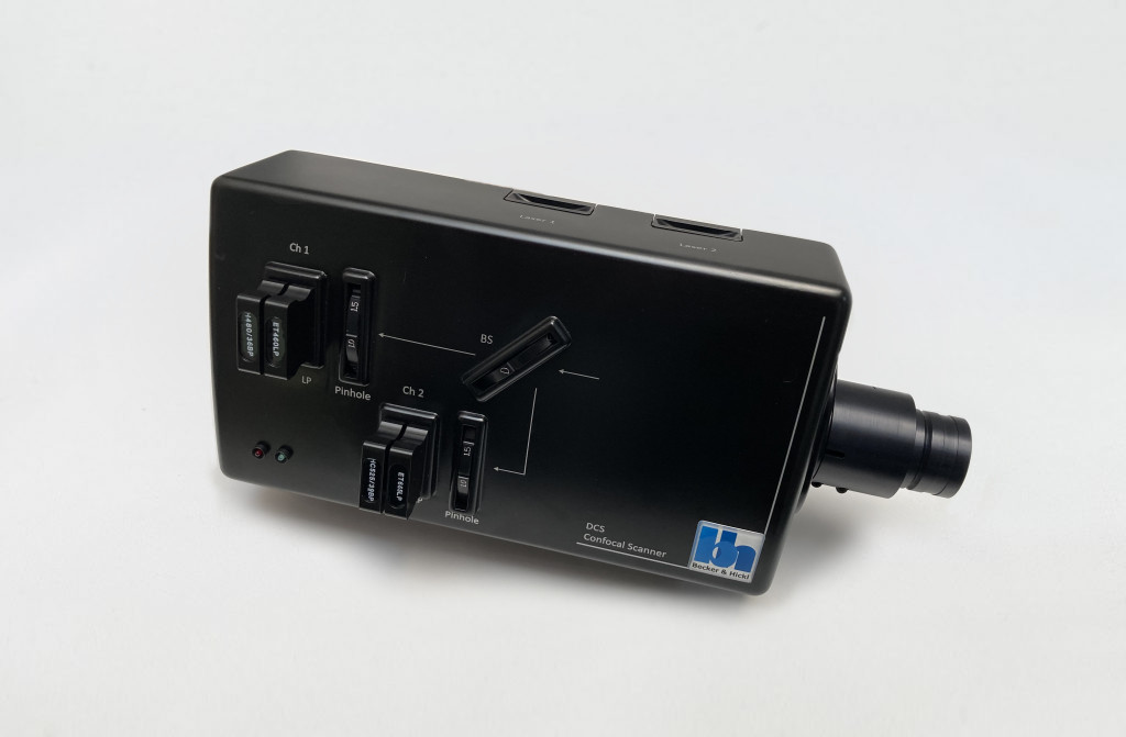
Scan Head
Optical Principle: Confocal, beam scanning by fast galvanometer mirrors
Laser Inputs: Two independent inputs, fibre coupled
Laser Power Regulation, Optical: Continuously variable via neutral-density filter wheels
Outputs to Detectors: Two outputs, detectors are directly attached
Main Beamsplitter Versions: Multi-band dichroic, wideband, multiphoton
Secondary Beamsplitter Wheel: Three dichroic beamsplitters, polarising beamsplitter, 100% to channel 1, 100% to channel 2
Pinholes: Independent pinhole wheel for each channel
Pinhole Alignment: Electronical, via piezo microstage
Pinhole Size: 11 pinholes, from about 0.5 to 10 AU
Emission Filters: Two filter sliders per channel in series
Connection to Microscope: Adapter to left side port or port on top of microscope
Coupling of ps Diode Lasers into Scan Head: Single-mode fibres, separate for each laser
Coupling of Ti:Sa or fs Fibre Laser into Scan Head, Multiphoton Systems: Free beam, 1 to 2 mm diameter
Scan Controller: bh GVD-120
Principle: Digital waveform generation, scan waveforms generated by hardware
Frame Size: Frame scan 16 x 16 to 2048 x 2048 pixels, line scan 16 to 2048 pixels
X Scan: Continuous or pixel-by-pixel
Y Scan: Line by line
Laser Power Control, Electrical: Software, electrical signals to lasers
Laser Multiplexing: Frame by frame, line by line, or within one pixel
Beam Blanking: During flyback and when scan is stopped
Scan Rate: Automatic selection of fastest rate or manual selection
Scan Area Definition: Via zoom factor and offset, or interactive via cursors during preview
Fast Preview Function: 1 second per frame, 256 x 256 pixels
Beam Park Function: Via cursor in preview image or cursor in FLIM image
Laser Multiplexing: Frame, line, or pixel multiplexing
TCSPC System: bh Simple Tau or Power Tau TCSPC system
Number of Parallel TCSPC / FLIM Channels: 2
TCSPC / FLIM Modules: SPC-150NX or SPC-180NX
Electrical Time Resolution: 1.5 ps RMS / 3.5 ps FWHM
Minimum Time Channel Width: 405 fs
Timing Stability Over 100 Seconds: Better than 0.8 ps RMS
Timing Stability Over 30 Minutes: Better than 5 ps RMS
Saturated Count Rate: 10 MHz per channel
Input from Detector: Constant-fraction discriminator
Reference (SYNC) Input from Laser: Constant-fraction discriminator
Synchronisation with Scanning: Via frame clock, line clock and pixel clock pulses
Scan Rate: Works with any scan rate
Synchronisation with Laser Multiplexing: Via routing function of TCSPC modules
Recording of Multi-Wavelength Data: Simultaneous in 16 channels, via routing function
Experiment Trigger Function: TTL, used for Z stack FLIM and microscope-controlled time series
Operation Modes of TCSPC System: Single f(t), oscilloscope, f(txy), f(t,T), f(t) continuous flow
FIFO (correlation / FCS / MCS) mode, Scan Sync In imaging, Scan Sync In with continuous flow
FIFO imaging, FIFO Imaging combined with MCS imaging, mosaic imaging, time-series imaging
multi-detector operation, laser multiplexing operation, cycle and repeat function, autosave function
Display Functions (Online): Intensity images, gated intensity images, lifetime images, decay curves in ROIs, decay curves, FCS curves, intensity traces.
No. of Images Displayed Simultaneously: 8
Max. Image Formats, Pixels X x Pixels Y x Time Channels: 2048 x 2048 x 256, 1024 x 1024 x 1024, 512 x 512 x 4096, 256 x 256 x 4096
Software:
Data Acquisition Software: bh SPCM
Scanner Control Software: Integrated in SPCM
Operating System: Windows 10 64 bit
Data Analysis Software: bh SPCImage NG
Principle of Data Analysis: MLE with GPU processing
Model Functions: Single, double, triple exponential decay, single, double, triple exponential decay with incomplete decay, shifted component model.
IRF Modelling: Syntethic IRF function fit to decay data
Excitation Sources, for Confocal FLIM: Two BDS-SM ps diode lasers
Available Wavelengths: 375 mm to 785 nm
Repetition Rate: 20, 50, 80 MHz and CW
Pulse Width: 40 ps to 100 ps
Detectors: HPM-100-40 hybrid detector with GaAsP cathode, 300 to 720 nm
Optional: HPM-100-06 detector with <20 ps FWHM IRF width, 300 to 650 nm
Optional: HPM-100-50 detector, 400 to 900 nm
Optional: MW-FLIM GaAsP multiwavelength detector
For Complete Specifications Please See:
DCS-120 Confocal and Multiphoton FLIM Systems, User Handbook
Downloads
Documents
Datasheets
Documents
- DCS-120 Confocal and Multiphoton FLIM Systems – User Handbook 9th ed. 2021
- DCS-120 Confocal and Multiphoton FLIM Systems – Overview Brochure
- FLIM Systems for Laser Scanning Microscopes – Overview Brochure
- The bh TCSPC Technique – Principles and Applications
- Bigger and Better Photons: The Road to Great FLIM Results
- SPCImage NG – Overview Brochure
- The bh FLIM Technique – More than Lifetime Imaging
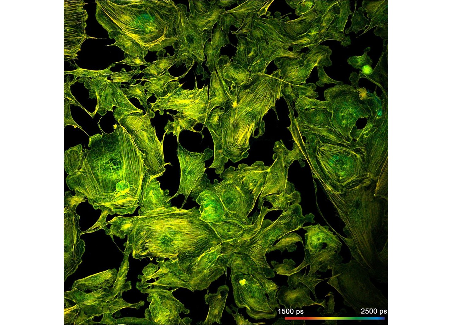
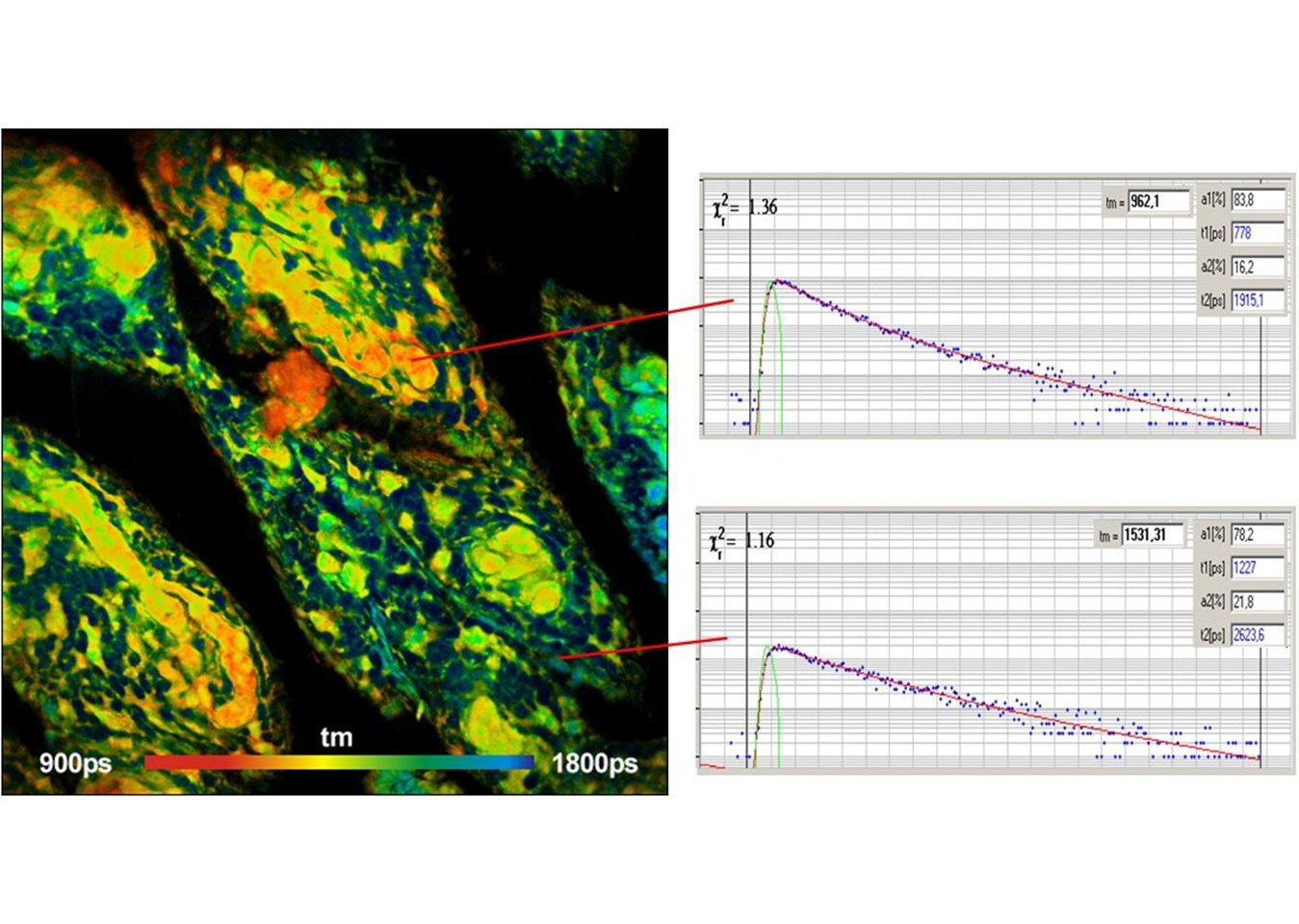
The realm of the bh FLIM systems is in molecular imaging. Typical applications are the imaging of ion concentrations, pH, or local viscosity, protein interaction experiments by FRET, and metabolic imaging by fluorescence decay of NADH an FAD in combination with oxygen measurement. In these applications, the bh FLIM systems benefit from their high sensitivity, high time resolution, high timing stability, and their capability to resolve multi-exponential-decay profiles into their components. Other advantages are the capability to record FLIM of fast physiological effects down to the millisecond range, and to record at several excitation and emission wavelengths simultaneously.
Applications
- Metabolic Imaging by FLIM
- FLIM of Fast Physiological Effects
- Molecular Imaging by FLIM
- FRET Imaging by FLIM
- Simultaneous Metabolic Imaging and pO2 Imaging
- Personalized Chemotherapy
- Fluorescence Correlation – FCS
- Antibunching Experiments by TCSPC
- TCSPC FLIM
- Multi-Wavelength FLIM
- Simultaneous FLIM / PLIM
- Fluorescence Cross Correlation – FCCS
Application Notes
- Recording Z Scans with the DCS-120 Confocal Scanning FLIM System
- An 8-Channel Parallel Multispectral TCSPC FLIM System
- Microsecond Decay FLIM: Combined Fluorescence and Phosphorescence Lifetime Imaging
- DCS-120 Confocal FLIM System with Wideband Beamsplitter
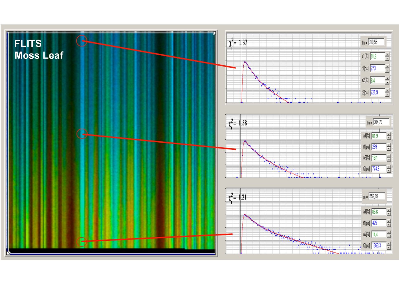
- Spatially Resolved Recording of Fluorescence-Lifetime Transients by Line- Scanning TCSPC
- DCS-120 Confocal Scanning System: FLIM with NIR Dyes
- Mosaic FLIM: New Dimensions in Fluorescence Lifetime Imaging
- Simultaneous Phosphorescence and Fluorescence Lifetime Imaging by Multi-Dimensional TCSPC and Multi-Pulse Excitation
- DCS-120 FLIM System Records X-Y Mosaics
- Metabolic Imaging with the DCS-120 Confocal FLIM System: Simultaneous FLIM of NAD(P)H and FAD
- Lifetime-Intensity Mode Delivers Better FLIM Images
- DCS-120 FLIM System Detects FMN in Live Cells
- SPCM Software Runs Online-FLIM at 10 Images per Second
- bh FLIM Systems Record Calcium Transients in Live Neurons
- Megapixel FLIM with bh TCSPC Modules – The New SPCM 64-bit Software
- TCSPC at Wavelengths from 900 nm to 1700 nm
- New SPCImage Version Combines Time-Domain Analysis with Phasor Plot
- Double-Exponential FLIM-FRET Approach is Free of Calibration
- A Common Mistake in Lifetime-Based FRET Measurement
- High Resolution Z-Stack FLIM with the Becker & Hickl DCS-120 Confocal FLIM System
Principles
Confocal Scanning
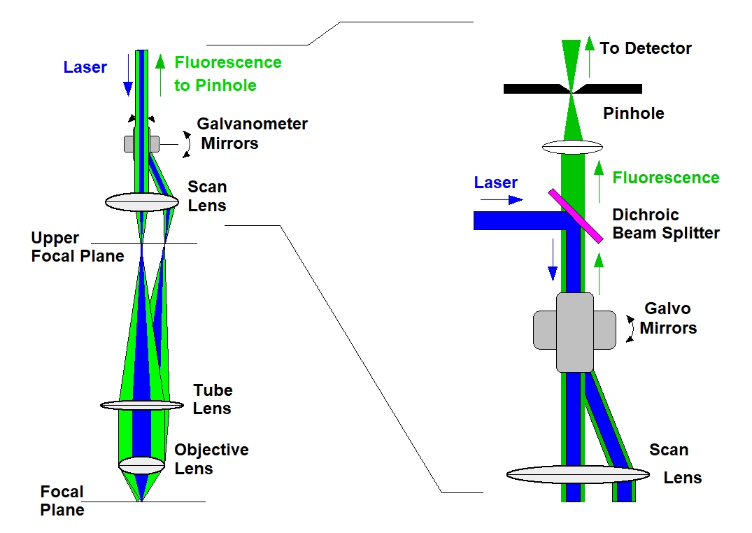
In a conventional fluorescence microscope fluorescence is excited and detected in a double cone throughout the entire depth of the sample, see figure below. The sharp image seen in the focal plane is therefore surrounded by out-of-focus haze from above and below the focal plane. For structural imaging of single cells this may still be acceptable. For FLIM, however, even a small amount of out-of focus blur is unacceptable because it adds unwanted decay components to the fluorescence decay in the focal plane. For FLIM of thick tissue the situation becomes entirely hopeless. The out-of-focus blur becomes entirely overwhelming, and results in an almost complete loss in image contrast and a total mixup of decay components.
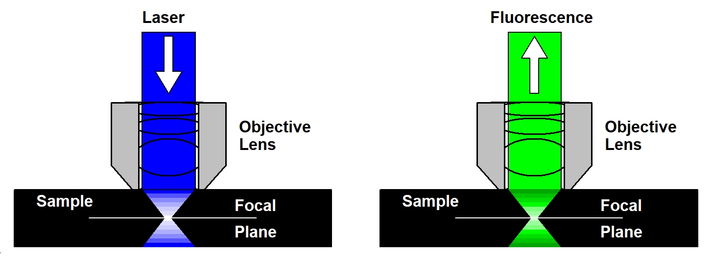
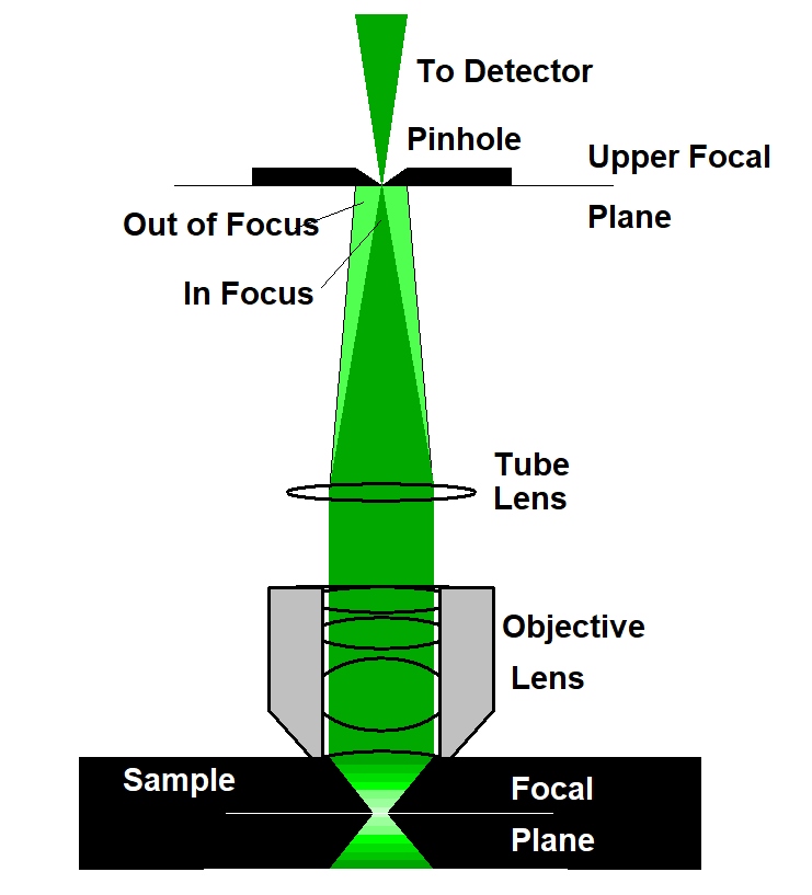
The solution to the out-of-focus problem is confocal detection. The principle is illustrated in the figure below, left. A laser beam is focused into the sample by the microscope objective lens. Although this beam excites fluorescence through the entire depth of the sample the fluorescence is brightest in the focus of the laser beam. The light from the focus of the laser beam is collected back through the microscope lens, separated from the laser beam by a dichroic mirror, and focused into a pinhole in the upper focal plane of the microscope lens. Only light from the focal plane can pass the pinhole - light from other planes is not focused into the pinhole and, consequently, cannot pass it with any appreciable efficiency.
Scanning
The principle of confocal detection solves the problem of out-of-focus light but, taken by itself, does not provide an image of the sample. To obtain an image of the an object in the focal plane confocal detection has to be combined with scanning. Scanning can be achieved by different techniques, such as moving the sample, moving the objective lens, or deflecting the laser beam and the detection beam by fast moving mirrors. The third option is the only one which is applicable to imaging of biological samples. It is fast, it does not exert mechanical forces to the sample, and it can be used for any object that can be placed under the microscope. Confocal detection in combination with beam scanning is illustrated in the figure below, left and right. The laser beam is deflected by a pair of fast-moving galvanometer mirrors. The scan lens projects the beam down towards the microscope lens. As the mirrors are moving, the beam angle in the plane of the microscope lens changes, and so does the position of the laser focus in the sample plane. The fluorescence goes back through the same beam path. Being reflected at the galvanometer mirrors, it forms a stationary beam of light coincident with the laser beam, see figure below, left. The fluorescence is separated from the laser by a dichroic mirror, and projected into a pinhole in a plane conjugate with the focal plane in the sample. Please see figure below, right.
As explained above, confocal detection in combination with scanning solves the problem of out-of-focus light in a microscope. However, scanning does more than that. It also avoids that light scattered in the sample causes lateral crosstalk between the pixels. Surprisingly, this is rarely mentioned in the microscopy literature. Consider an imaging system that simultaneously illuminates the entire sample and detects an image from the focal plane by a camera. In all pixels of this image the camera will detect scattered light from all other pixels in the illuminated area, see below, left. A scanning system - scanning the sample by a focused laser beam and detecting light only from the excited spot - records only light from the current pixel (right). Even if a part of this light is scattered in the sample the imaging system will assign the scattered photons to the correct pixel.
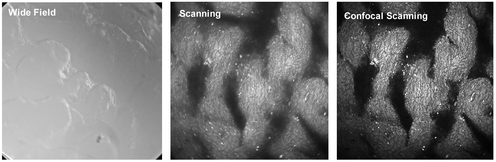
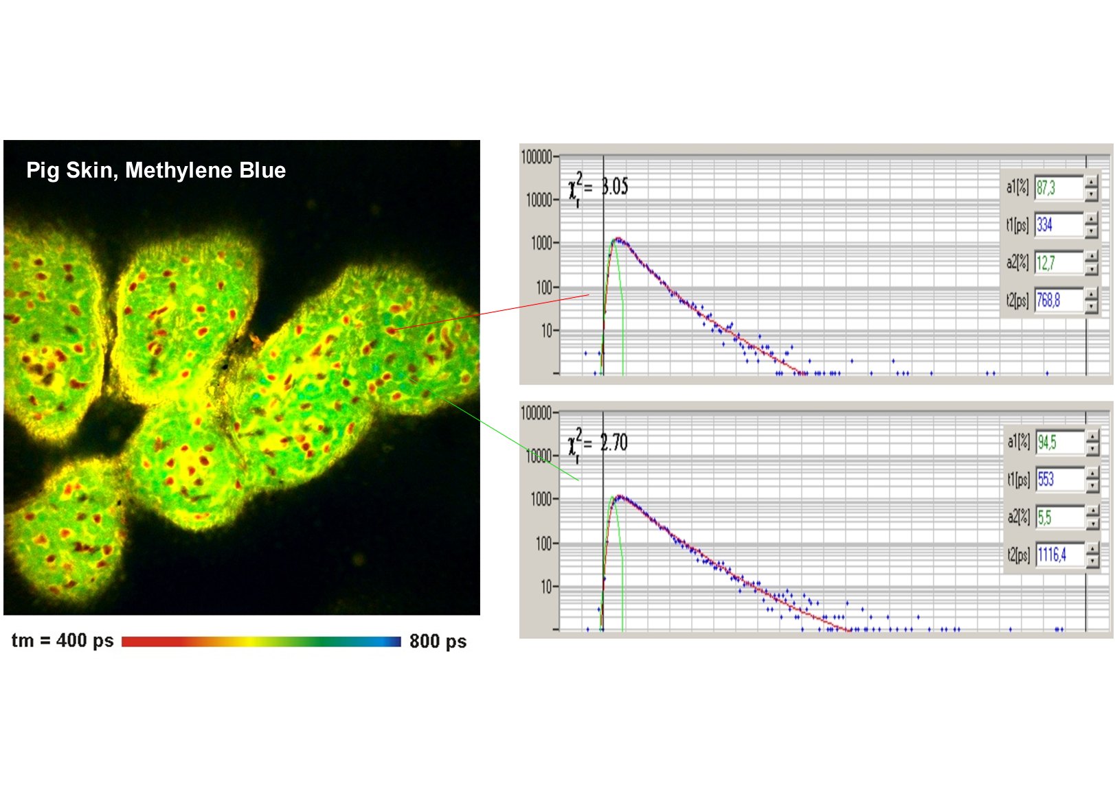
The supression of laterally scattered light means that already scanning alone - without the help of confocal detection - massively improves the image quality in optically thick samples. An example is shown in the figure below. From left to right, it shows images of a pig skin sample recorded by an ordinary camera, by scanning and detection without a pinhole, and by confocal detection though a pinhole. The camera image (left) shows nothing from inside the sample, the scan image (middle) shows the internal structure, and the confocal image (right) shows the internal structure without out-of-focus haze.
Combination with TCSPC FLIM
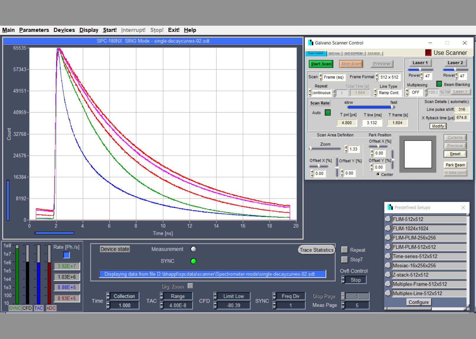
The bh FLIM systems use a multi-dimensional TCSPC technique. That means, single photons of the light passing the pinhole are detected, the times of the photons within the excitation pulse period and the position of the laser beam in the moment of the photon detection are determined, and a photon distribution over these parameters is build up. The result is an array of pixels, each containing photon numbers in a large number of consecutive time channels. Please see figure below.
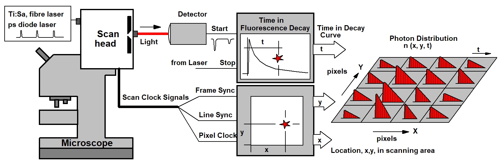
The TCSPC-FLIM recording process works at any scan rate, achieves a near-ideal photon efficiency, delivers a beautifully resolved decay function in every pixel, and reaches an extremely high time resolution. The signal-to-noise ratio depends only on the photon rate available from the sample and the total acquisition time. By adding additional dimensions to the photon distribution, multi-wavelength FLIM images, multi-excitation-wavelength images, combined fluorescence / phosphorescence image, and images of fast physiological effects in the sample can be accumulated. As all bh FLIM systems, the DCS-120 TCSPC system has two parallel TCSPC channels detecting in different wavelength intervals or under different angle of polarisation.
Please see The bh TCSPC Handbook and Handbook of the DCS-120 Confocal and Multiphoton FLIM Systems for details.
Gallery