- Single-Transversal Mode Picosecond and CW Diode Laser
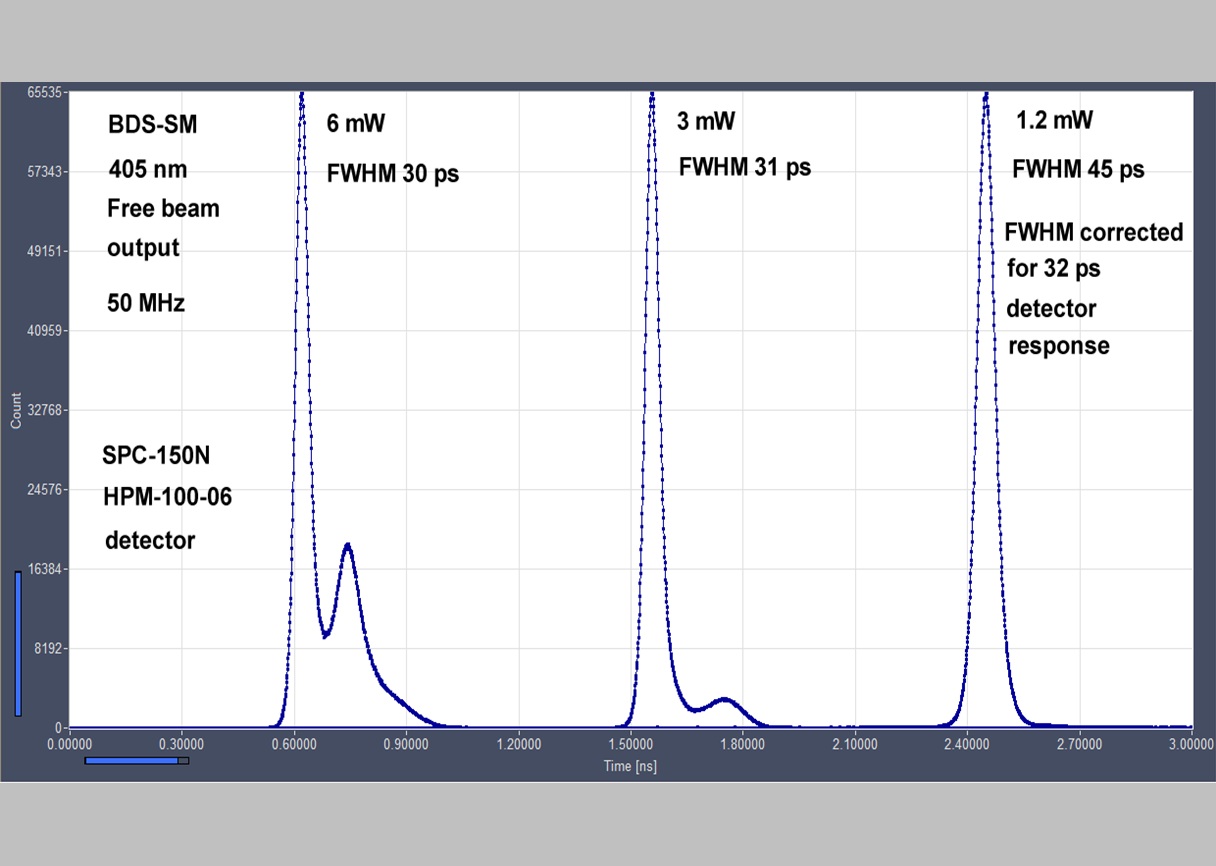
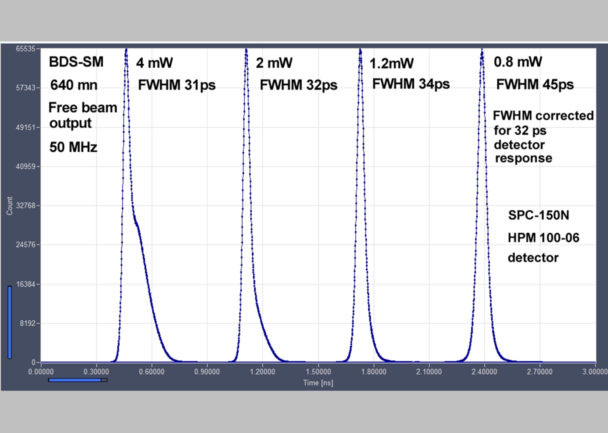
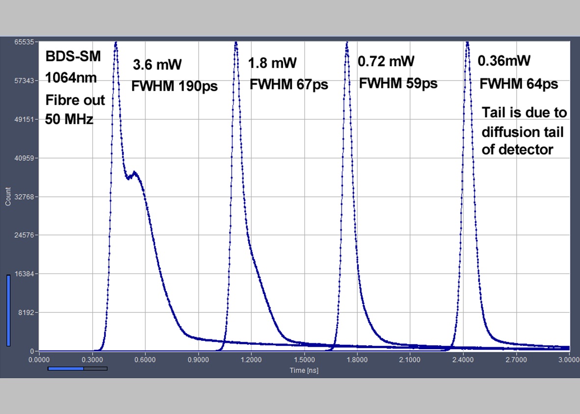
- Pulse Width Down to 30 ps
- Excellent Timing Stability - No Warm-Up Time Necessary
- Optical Power up to 5 mW in Pulsed Mode
- Optical Power up to 50 mW in CW Mode
- Free Beam or Single-Mode Fiber Output
- Repetition Rate 20 MHz / 50 MHz / 80 MHz / CW (Switchable)
- Trigger Input for Synchronisation to External Clock Sources
- Internal Power Stabilization Loop
- Fast ON / OFF / Multiplexing Capability
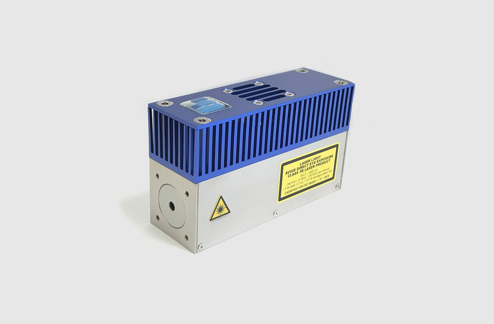
- All Electronics Integrated in 40 x 40 x 120 mm Case
- No External Driver Unit Required
- Simple +12 V Supply
- 40 x 40 x 120 mm3 or 40 x 70 x 120 mm3
Description
General Features
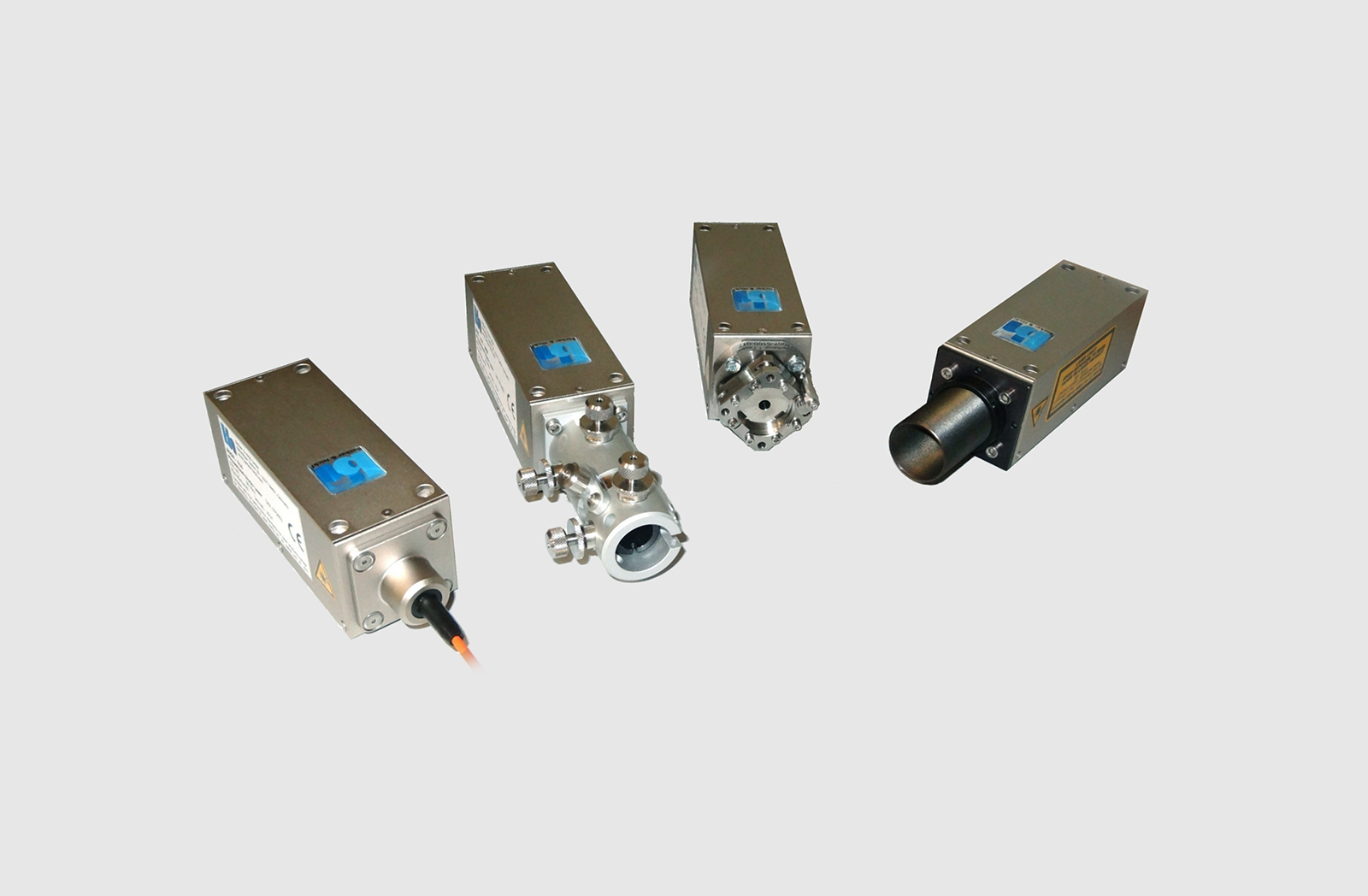
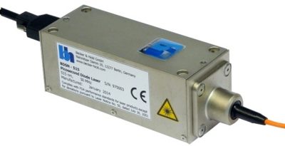
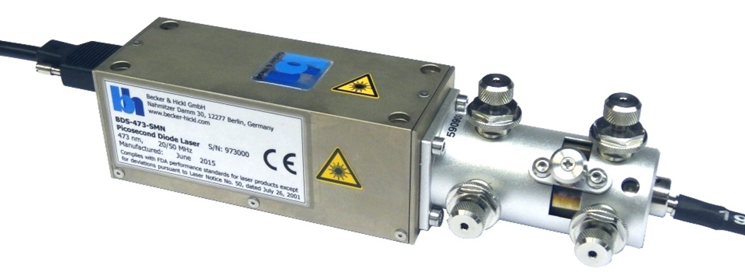
The BDS-SM devices are combined pulsed picosecond and CW diode lasers in a small industrial-size case. All the pulse driver and control circuitry is contained in the laser head. All that is needed to operate the lasers is a +12V power supply and a few control signals for setting repetition rate and optical power. Pulse repetition rate in pulsed mode is 20, 50, or 80 MHz, other repetition rates are available on request or can be obtained by external triggering. Pulse width is in the range of 40 ps to 100 ps.
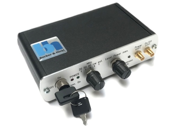
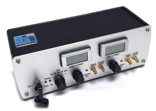
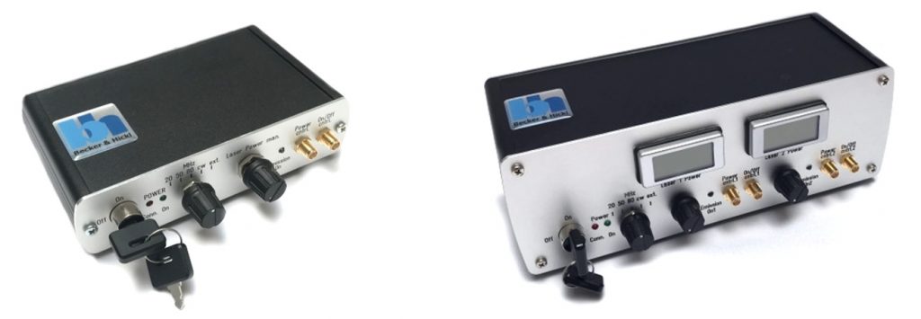
Laser Switch Box
In OEM applications the laser head can be embedded as it is, with the the external system providing the control signals. For stand-alone applications the LSB-C laser switch box or the LSB-C2 dual-laser switch boxes are available, see photos below. Software-generated control signals can be provides by the bh DCC-100 and DCU-400/800 detector/laser controllers.
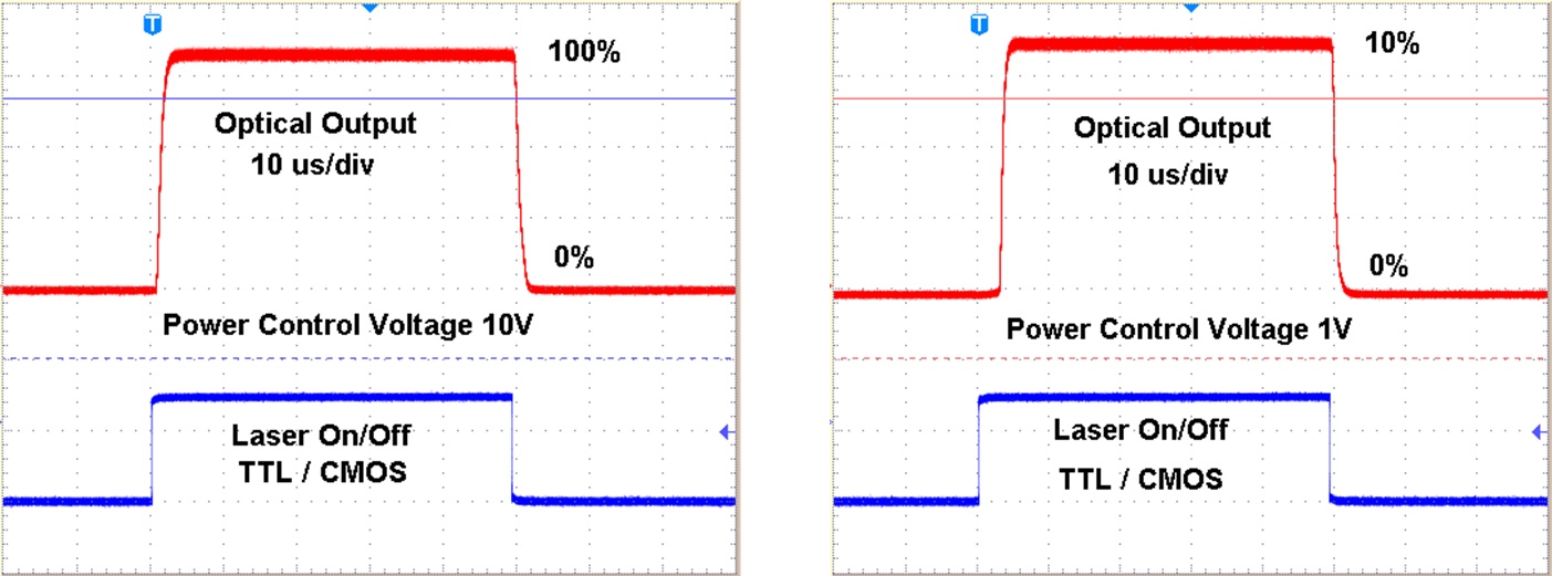
Internal Power-Regulation Loop and Fast ON/OFF Function
Due to an internal power regulation loop, the BDS-SM lasers feature extraodinarily stable optical power. Intensity drift by temperature changes and intensity noise by mode fluctuations in the laser diode are almost entirely suppressed. The lasers have a fast on/off function which can be used for beam blanking in scanning applications and for laser multiplexing. The reaction of the optical output power to the ON/OFF control for 100% power and for 10% power is shown below. Horizontal scale is 10 microseconds per division.
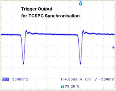
Trigger Output
The BDS-SM lasers deliver a trigger output signal for synchronisation to bh TCSPC devices, see figure below. The output amplitude is sufficient for distribution of the trigger signal to several TCSPC modules. The timing stability of the trigger pulses versus the optical pulses is better than 5 ps. Extended warm-up times are not needed. After switch-on of the power supply, the timing is stable within about 4 picoseconds.
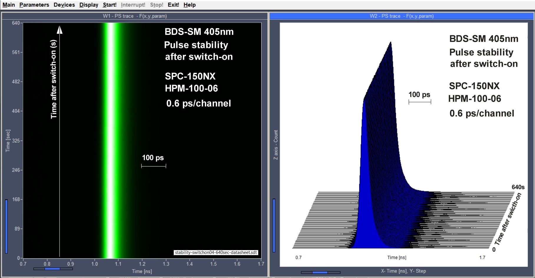
Timing Stability
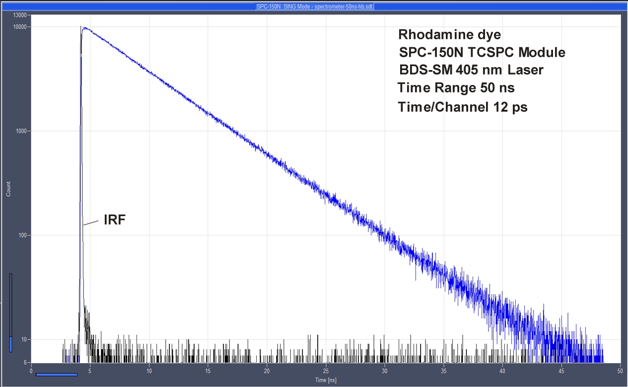
The bh BDS-SM series picosecond diode lasers feature a timing stability in the sub-4ps range. The figure below shows a series of TCSPC recordings of the laser pulses over a period of 640 seconds after power-on of the laser. The left panel shows the data displayed in colour-intensity mode, the right panel in multi-curve mode. The example below shows that timing drift, if present at all, is far smaller than the laser pulse width of 49 ps FWHM. That means TRS, FLIM, or NIRS experiments can be started from the first second after turning on the laser, and do not require repeated reference measurements.
Synchronisation to External Trigger Signal
The BDS-SM lasers can be triggered externally. To keep the internal power regulation loop in the active range the trigger frequency should be in the range from 10 to 80 MHz. The laser switches between the external trigger signal and the internal 20-50-80 MHz clock by sensing the average voltage at the synchronisation input. If the average voltage is above 2.5 V the laser uses the internal clock, if it is below 2.5 V it synchronises to the external signal.
Optical Output
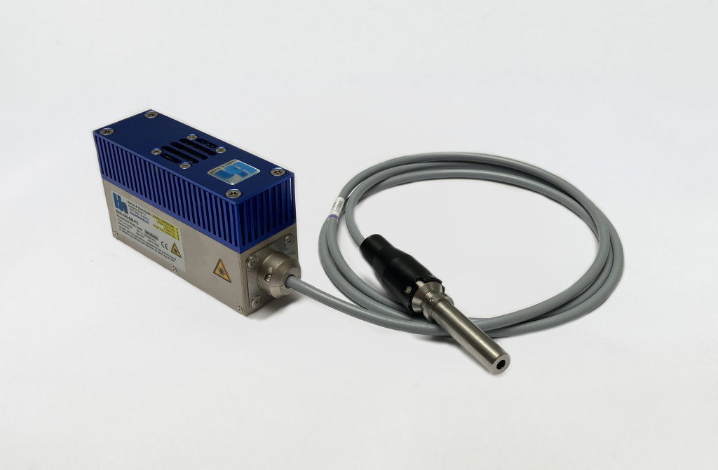
All BDS-SM lasers are tansversal single-mode lasers. That means, the emission virtually comes from a single spot inside the laser. That means the laser beam can be focused in a diffraction-limited spot or coupled into a single-mode fibre. The BDS-SM lasers are available with free-beam output, with fixed (pig tail) fibres, with Lasos Precision fibre connectors, and with Point-Source-Type couplers. An example of fibre coupling is shown in the figure below.
Specifications
|
|
BDS-SM |
|
Optical |
|
|
Wavelength / nm |
375, 405, 445, 473, 485, 515, 640, 685, 785, 1024, Other on Request |
|
Repetition Rate |
20, 50, 80 MHz and CW Operation, Other on Request |
|
Pulse Width (FWHM, at Medium Power, at Maximum Power) |
30 - 90 ps, 60 - 300 ps |
|
Power Control Range (Power in Free Beam) |
0 to 1 mW … 0 to 5 mW (Depends on Wavelength Version) |
|
Power Control Range (CW Mode, Power in Free Beam) |
0 to 20 mW … 0 to 50 mW (Depends on Wavelength Version) |
|
Diameter of Laser Beam (Free Beam) |
0.8 mm (Circular) or 1 x 3 mm (Elliptical, Depends on Version) |
|
Beam Configuration |
Transversal Single Mode |
|
Polarisation |
Horizontal |
|
Coupling Efficiency into Single-Mode Fiber (typ.) |
Up to 60 % (Circular-Beam Version) |
|
Trigger Output |
|
|
Pulse Amplitude |
-1.2 V (Peak) into 50 Ω |
|
Pulse Width |
1 ns |
|
Output Impedance |
50 Ω |
|
Connector |
SMA |
|
Jitter between Trigger and Optical Pulse |
< 5 ps RMS |
|
Timing Stability, Trigger to Optical Pulse |
< 5 ps RMS |
|
Timing Drift after Power-On |
< 5 ps |
|
Synchronisation Input |
|
|
Input Amplitude |
+3.3 V to +5 V into 50 Ω |
|
Duty Cycle |
10 to 30 %; DC Equivalent must be < 2.5 V |
|
Input Frequency |
Single shot to 80 MHz |
|
Switching from Internal Clock to Sync Input |
Automatic, by Average Voltage at Trigger Input Connector |
|
Control Inputs |
|
|
Frequency (20, 50, 80 MHz) and CW Operation |
TTL / CMOS high |
|
Laser ON / OFF |
TTL / CMOS low |
|
Response of Optical Output to ON/OFF Signal |
< 4 µs for Power 10 to 100 % |
|
External Power Control |
Analog Input, 0 to +10 V |
|
Response Time of Optical Output to Power Control |
< 4 µs for Power 10 to 100 % |
|
Power Supply |
|
|
Power Supply Voltage |
+9 V to +15 V |
|
Power Supply Current at 12 V |
200 mA to 500 mA 1) |
|
Mechanical Data |
|
|
Dimensions (OEM) |
40 mm x 40 mm x 120 mm |
|
Dimensions (w/ Cooling) |
40 mm x 70 mm x 120 mm |
|
Mounting Thread |
four M3 Holes |
|
Heat Sink Requirements |
< 2 °C / W 2) |
|
Maximum Values |
|
|
Power Supply Voltage |
0 V to +15 V |
|
Voltage at 'Laser ON/OFF' and 'Frequency' Inputs |
-2 V to +7 V |
|
Voltage at 'Laser Power' Input |
-12 V to +12 V |
|
Ambient Temperature |
15 °C to +40 °C |
(1) Depends on case temperature due to laser diode cooling. Cooling current changes with case temperature.
(2) OEM version without cooling fan must be mounted on heat sink. Case temperature must remain below 40 °C.
Downloads
Documents
Applications
Application Notes
- Two-Photon Fluorescence Excitation by Picosecond Diode Lasers
- Recording the Kautsky Effect by Fluorescence Lifetime Detection
- Timing Stability of TCSPC Experiments
- bh FLIM Systems for Nikon C1 Scanners
- Recording Z Scans with the DCS-120 Confocal Scanning FLIM System
- Microsecond Decay FLIM: Combined Fluorescence and Phosphorescence Lifetime Imaging
- DCS-120 Confocal FLIM System with Wideband Beamsplitter
- DCS-120 Confocal Scanning System: FLIM with NIR Dyes
- TCSPC at Wavelengths from 900 nm to 1700 nm
- FLIM and FCS by Pulse-Interleaved Excitation with the Zeiss LSM 710/780 Intune System
- NSOM FLIM with the Nanonics AFM/NSOM System
- Implantable Fibre-Optical Fluorescence-Lifetime Detection System for in-vivo Applications
- TCSPC Fibre-Probe System with an Exchangeable Tip
- The PZ-FLIM-110 Piezo-Scanning FLIM System
- 80 ps FHWM Instrument Response with ID230 InGaAs SPAD and SPC-150 TCSPC Module
- Wide-Field TCSPC FLIM with bh SPC-150N TCSPC System and Photek FGN 392-1000 Detector
- TCSPC System Records FLIM of a Rotating Object
- Metabolic Imaging with the DCS-120 Confocal FLIM System: Simultaneous FLIM of NAD(P)H and FAD
- Software-Integrated FLIM for Nikon A1+ Confocals
- An AFM/NSOM System with Fluorescence Lifetime Imaging
- bh TCSPC Systems Record FLIM with Sutter MOM Microscopes
- High-Resolution LIDAR with the SPC-QC-104
Gallery