FLIM with
Excitation-Wavelength Multiplexing
W.
Becker, Lukas Braun, Cornelia Jubghans, Axel Bergmann, Becker & Hickl GmbH
Abstract: Laser wavelength multiplexing is used for
simultaneous FLIM of several fluorophores with different excitation spectra.
Lasers of different wavelength are alternatingly switched on and off
synchronously with the frames, the lines, or the pixels of the scan. The TCSPC
process marks each photon with an identifier of the laser or laser wavelength
that was active in the moment of the detection. It then uses this information
to build up separate images for the individual lasers. Applications are
simultaneous measurements of cell parameters with several spectroscopic markers
and measurements of the complex behaviour of live systems over time.
Motivation
For many years, FLIM has been focusing on
the determination of single cell or tissue parameters via their influence on
the fluorescence-decay function of a special molecular probe. However, in the
past 10 years, FLIM experiments have become considerably more complex. The task
is now to record the complex behaviour of live systems as a function of time, of
the environment conditions, or the phase in the cell cycle. The experiment then
usually involves simultaneous recording of signals from several endogenous or
exogenous fluorophores. Things remain relatively straightforward as long as the
fluorophores can be excited at the same wavelength but fluoresce in different
emission wavelength intervals. If this is not the case, either because there is
no overlap in the excitation spectra or
too much overlap in the emission spectra, different excitation wavelengths have
to be used. A possible solution is to run several measurements one after
another with different lasers or with the laser tuned to different wavelengths.
However, laser-induced changes in the sample can then make the results
difficult to compare. Moreover, it is not possible to record physiological
effect on a time scale faster than a few minutes.
It is therefore desirable to multiplex the
laser wavelengths at high rate, i.e. quickly switch back and forth between the
laser wavelengths and record the signals into separate photon distributions [1]. Generally, there are two ways to perform this kind
of measurement: The lasers can be multiplexed pulse by pulse or they can be
multiplexed within a period comparable to the frame, line, or pixel times of
the scan. Advantages and disadvantages of the two techniques are described in [1]. Here we refer to the second technique because it
does not require a reduction of the laser pulse rate, is free of crosstalk by
overlap of the tails of the decay functions, and has no intensity crosstalk by
pile-up and counting-loss effects. The principle is illustrated in Fig. 1.
Fig. 1: Laser wavelength multiplexing by on/off modulation of lasers.
Left: Laser wavelengths and detection wavelength intervals. Right: Laser ON/OFF
switching and detected signals.
In Fig.
1 both laser wavelengths are shown on the
short-wavelength side of the detection-wavelength intervals. However, if the
right beamsplitters and filters are used one laser wavelength can also be
between the two detection wavelength intervals.
Recording Principle
Laser-multiplexed FLIM uses the
multi-dimensional recording capability of the bh TCSPC technique [1, 2]. The principle for multiplexing two lasers is shown
in Fig. 2. The lasers are on/off modulated synchronously with
the pixels, lines, or frames of the scan. A routing signal is sent into the
TCSPC module to indicate which laser was active at the moment when a photon was
detected. The TCSPC module uses this information to direct the photons into
different photon distributions. In other words, the laser wavelength is used as
an additional coordinate of the photon-recording process. With two TCSPC / FLIM
modules running in parallel, data for four combinations of excitation and
emission wavelength are obtained, see Fig.
2. The technique is not restricted to two lasers or two
TCSPC modules, in principle any number of laser wavelengths or TCSPC modules
can be used [1]. To avoid interference of the laser multiplexing
with the scanning the on/off modulation of the lasers is synchronised with the
pixels, lines, or frames of the scan. Please see [1] for further technical details.
Fig. 2: FLIM with laser multiplexing. Two lasers are multiplexed in time,
and the photons are recorded by two TCSPC modules. The result is four images with
different combination of excitation and emission wavelength.
Laser Multiplexing with the DCS-120 System
Laser multiplexing is a standard function
of the bh DCS-120 confocal FLIM systems [3]. The systems have two ps diode lasers and two TCSPC
channels, i.e. the structure is exactly as shown in Fig. 2. Laser on/off control is implemented in the GVD-120
scan controller. The multiplexing function is accessible via the scan control
panel, see Fig. 3, left. In the example shown, frame multiplexing was
selected. To direct the photons in separate FLIM images, Routing Channels = 2
has to be selected in the SPCM System Parameters, see Fig. 3, middle. The 3D Trace Parameters were set to display
images for all four combinations of laser (Routing: 1, 2) and
detection wavelengths (TCSPC Module: M1, M2). The images are displayed as
colour-coded lifetime images (Type: LIFET), using the online-lifetime function
of SPCM.
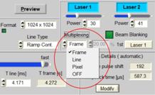
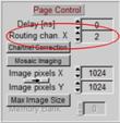
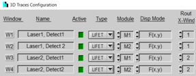
Fig. 3: Parameters for Laser Multiplexing. Left: Scan parameters, Frame
Multiplexing selected. Middle: Page Control in SPCM System Parameters: Two
routing channels defined. Right: 3D Trace parameters: 4 images defined, for four
combinations of lasers (Routing Window) and TCSPC modules (M1, M2). Images are
displayed as coulour-coded lifetime images (Type = LIFET).
Fig.
4. demonstrates laser multiplexing on a BPAE sample
(available from Invitrogen). The sample contains DAPI (excitable at
405 nm) and Alexa 488 (excitable at 488 nm). For the result shown in Fig. 4 the sample was excited by lasers of 405 nm and
480 nm in the frame-multiplexing mode. The image on the left is the Alexa
image, excited by 480 nm and detected from 510 nm to 580 nm. The
middle image shows the DAPI, excited by 405 nm, and detected from 430 nm
to 470 nm. The image on the right shows data excited at 405 nm but
detected in the ALEXA emission range. It shows emission both from DAPI and from
Alexa 488. The fourth image (not shown), excited at 488 nm and detected
from 430 nm to 470 nm, does not contain data because the detection
wavelength is shorter than the excitation wavelength.
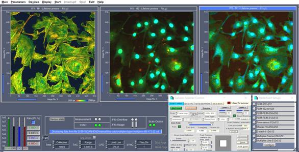
Fig. 4: Excitation wavelength multiplexing, SPCM main panel showing images
of three combinations of excitation and detection wavelength. Online-lifetime
display of SPCM software.
The system parameter settings for line and pixel
multiplexing are, by and large, similar to the settings shown above. However,
the lasers are now running alternatingly in every second line or every second
pixel. Laser one is running in the uneven lines (pixels), laser 2 in the even
lines (pixels). To build up a correct image the SPC modules have to combine two
lines of the scan into one line of the photon distribution. The combination is
defined in the More Parameters panel of the SPCM system parameters, see Fig. 5, right. With the setup parameters shown the recording
process splits the data of a 512 x 512 pixel scan with line multiplexing into
two 256 x 256 pixel images for the individual lasers. For details, please refer
to [3], chapter Advanced Techniques and Procedures.
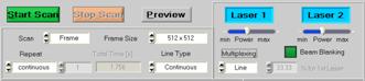

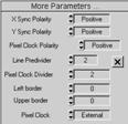
Fig. 5: Parameter setup for laser multiplexing, line by line. The data of
a 512 x 512 pixel scan are split into two 256 x 256 pixel images for the
individual lasers.
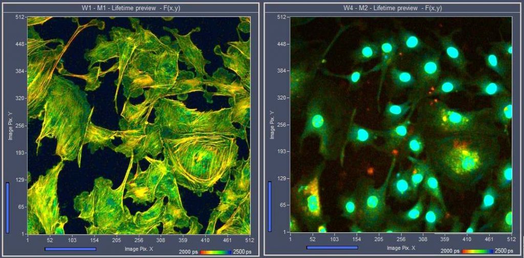
Simultaneous FLIM of NADH and FAD
An important (if not the most important)
application of excitation-wavelength multiplexing is simultaneous recoding of
NADH and FAD FLIM. The decay functions of NADH and FAD change with the
metabolic state of the cells or tissues. More reductive metabolism, as it
exists in tumors, increases the amplitude of the fast decay component of NADH
and decreases the amplitude of the fast decay component of FAD. More oxidative
metabolism, as it is typical of normal cells, has the reverse effect [1]. Because the effect for NADH and FAD goes in
different directions FLIM data are meaningless unless the signals are clearly
separated. However, exactly this is the problem. Both the excitation spectra
and the emission spectra are strongly overlapping. A separation of the signals
can be achieved, however, if NADH is excited at 370 nm and detected from
420 to 475 nm, and FAD is excited between 410 to 450 nm and detected
at 490 nm and higher [1]. For reasons of data compatibility it is desirable
to record the NADH and FAD images simultaneously, hence the solution is FLIM
with excitation-wavelength multiplexing. An example is shown in Fig. 6.
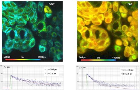
Fig. 6: Simultaneous FLIM of NADH (left) and FAD (right) by laser-wavelength
multiplexing and dual-channel detection. Fluorescence decay curves in selected
spots shown at the bottom.
The data were recorded with a DCS-120
confocal scanning FLIM system in the configuration shown in Fig. 2. The laser wavelengths were 370 nm for NADH
excitation and 410 nm for FAD excitation. Please see [1, 4] for
details. For application of the system and comparison of FLIM results with
histology please see [1], chapter autofluorescence FLIM of cells and
tissues, and [7, 8].
Laser Multiplexing with the LHB-104 Laser Hub
The LHB-104 Laser Hub contains four bh
BDS-SM series picosecond diode lasers [5]. The optical outputs of the lasers are combined into
one single-mode fibre. Part of the LHB-104 electronics is a multiplexing module
(MPM). The MPM can be used to multiplex each two of the four lasers synchronously
with the pixel, line, or frame clock pulses of a laser scanning microscope.
Therefore, multiplexing is not restricted to the DCS-120 or other systems that contain
a bh GVD-120 scan controller. Multiplexing of lasers by the MPM can be used in
combination with any laser scanning microscope, in particular with the Zeiss
LSM 980 [6]. The principle of the MPM is shown in Fig. 7. A toggle flip-flop is triggered by of one of the
scan clocks, Frame, Line, or Pixel. Every time when a clock pulse arrives, the
flip-flop changes its state. The outputs of the flip-flop switch two lasers,
Laser 1 and Laser 2, on and off alternatingly. Simultaneously, the MPM sends a
routing bit to the TCSPC system to route photons excited by different lasers
into separate memory blocks. The multiplexing mode, i.e. frame, line, or pixel
multiplexing, is selected by the Mode switch. For details please see [5] and [6].
Fig. 7: Principle of the Laser Multiplexing Module in the LHB-104
An example is shown in Fig. 8. A convallaria sample was excited at 480 nm
(left) and 405 nm (right). The lasers were multiplexed frame by frame. Both
images were detected in one spectral channel, from 510 to 590 nm.
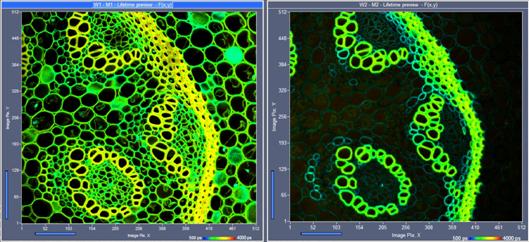
Fig. 8: FLIM of a convallaria sample, multiplexed excitation at 488 nm and
405 nm
Excitation Multiplexing with Femtosecond Fibre Laser
Multiplexed excitation can be performed
also with a number of other lasers. One of them is the Toptica Femto Fibre
Dichro. This laser generates two wavelengths, 785 nm and 880 nm. The
pulse width is less than 200 fs. Each of the two beams passes an AOM to
regulate the intensity or to switch on and off the beams. At the output of the
laser the two beams are combined by a dichroic beam combiner. With its two
wavelengths, its short pulse width, and its ability to on/off modulate the
outputs the Femto Fibre Dichro is ideally suited for 2-photon NADH / FAD FLIM,
please see [1].
Two-photon images of pig skin recorded with the Femto Fibre Dichro and the
DCS-120 MP system [3] are shown in Fig.
9 and Fig.
10. The data quality is so high that the parameters of
the decay components can be exctracted by double-exponential decay analysis.
The NADH data are shown in the upper row, the FAD data in the lower row. From
left to right, the images show the amplitude of the fast decay coponent, a1,
the lifetime of the fast decay component, t1, and the lifetime of the slow
decay component, t2.
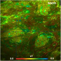
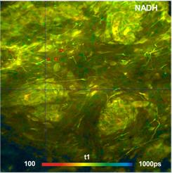
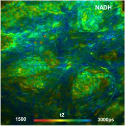
Fig. 9: FLIM images of pig skin
recorded with a Femto Fibre Dichro connected to a DSC-120 MP system. NADH
images, left to right: amplitude of the fast decay coponent, a1, lifetime of
the fast decay component, t1, and lifetime of the slow decay component, t2.
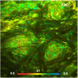
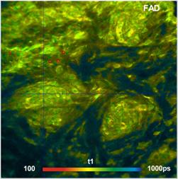
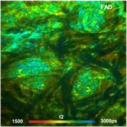
Fig. 10: FLIM images of pig skin recorded with a Femto Fibre Dichro
connected to a DSC-120 MP system. FAD images, left to right: amplitude of the
fast decay coponent, a1, lifetime of the fast decay component, t1, and lifetime
of the slow decay component, t2. Data analysis by SPCImage NG.
Supercontinuum Lasers with AOTF
Wavelength multiplexing can also be
performed with a supercontinuum laser and an acousto-optical filter (AOTF).
Please see [1] for
a demonstration of the method. A problem in fluorescence applications can be
side-band leakage of the AOTF. The leakage usually has to be be removed by
cleaning filters in the excitation beam path, with the effect that the
flexibility of wavelength selection by the AOTF is lost. AOTF leakage is less a
problem on diffuse-optical imaging applications. A system that multiplexes 8
wavelengths via an AOTF and records the diffusely reflected light has been described
in [1], chapter Diffuse Optical Tomography.
Summary
Excitation-wavelength
multiplexing is an efficient way to record FLIM data of several fluorophores
with different excitation spectra simultaneously. Compared with sequential
recording at different excitation wavelength the advantage is that possible
laser-induced changes, focus drift, or motion in the sample have comparable
effects on the FLIM data of all laser wavelengths. So far,
excitation-multiplexed FLIM has been shown to be a promising technique for
metabolic imaging [1, 7, 8]. However, the technique has an even larger
potential. The multiplexing rate can be the order of 1 Hz, 1 kHz, or
several 100 kHz for frame, line, and pixel multiplexing, respectively. Multiplexing
therefore does not conflict with time-series recording. Even temporal mosaic
FLIM with a resolution in the range of 50 ms per image appears feasible.
FLIM with excitation-wavelength multiplexing is therefore a solution for the
investigation of physiological effects, effects of environment conditions or drugs
on the cell metabolism, or photodynamic-therapy effects.
References
1.
W. Becker, The bh TCSPC
handbook. 8th edition (2019), available on www.becker-hickl.com
2.
Becker & Hickl GmbH, The bh
TCSPC Technique. Principles and Applications. Available on
www.becker-hickl.com.
3.
Becker & Hickl GmbH,
DCS-120 Confocal and Multiphoton Scanning FLIM Systems, user handbook 8th ed.
(2019). Available on www.becker-hickl.com
4.
W. Becker, A. Bergmann, L.
Braun, Metabolic Imaging with the DCS-120 Confocal FLIM System: Simultaneous
FLIM of NAD(P)H and FAD, Application note, available on www.becker-hickl.com
(2018)
5.
Becker & Hickl GmbH,
LHB-104 Laser Hub. User Manual. Available on www.becker-hickl.com.
6.
Becker & Hickl GmbH,
FLIM Systems for Zeiss LSM 980 Laser Scanning Microscopes. Addendum to:
Handbook for modular FLIM systems for Zeiss LSM 710 / 780 / 880 family
laser scanning microscopes. Available on www.becker-hickl.com
7.
Rodrigo Suarez-Ibarrola, Lukas
Braun, Philippe Fabian Pohlmann, Wolfgang Becker, Axel Bergmann, Christian
Gratzke, Arkadiusz Miernik, Konrad Wilhelm, Metabolic Imaging of Urothelial
Carcinoma by Simultaneous Autofluorescence Lifetime Imaging (FLIM) of NAD(P)H
and FAD. Clinical Genitourinary Cancer (2020)
8.
Becker Wolfgang, Suarez-Ibarrola
Rodrigo, Miernik Arkadiusz, Braun Lukas, Metabolic Imaging by Simultaneous FLIM
of NAD(P)H and FAD. Current Directions in Biomedical Engineering 5(1), 1-3
(2019)
Contact:
Wolfgang Becker
Becker & Hickl GmbH
Berlin, Germany
Email: becker@becker-hickl.com