- Three Parallel TCSPC Channels + One Sync / Reference Channel or Four Parallel Absolute Timing Channels
- Time Channel Width Down to 4 ps
- IRF Width <39 ps FWHM
- Typical Timing Jitter 16 ps RMS
- Excellent Timing Stability: Timing Drift over 10 Minutes <5 ps RMS
- Low Dead Time
- Adjustable SYNC Delay ± 128 ns
- High Peak Count Rate, up to 120 MHz
- Parallel Fluorescence Decays in up to Three Detection Channels
- Recording of Fluorescence Decay and Other Optical Waveforms
- Multi-Wavelength Detection of Fluorescence Decay Data
- Photon Time- and Parameter Tagging
- Photon Correlation Down to the ps Range
- Free Instrument Software for Windows 10 / 11
- Custom Programming with bhPy
Description
General Information
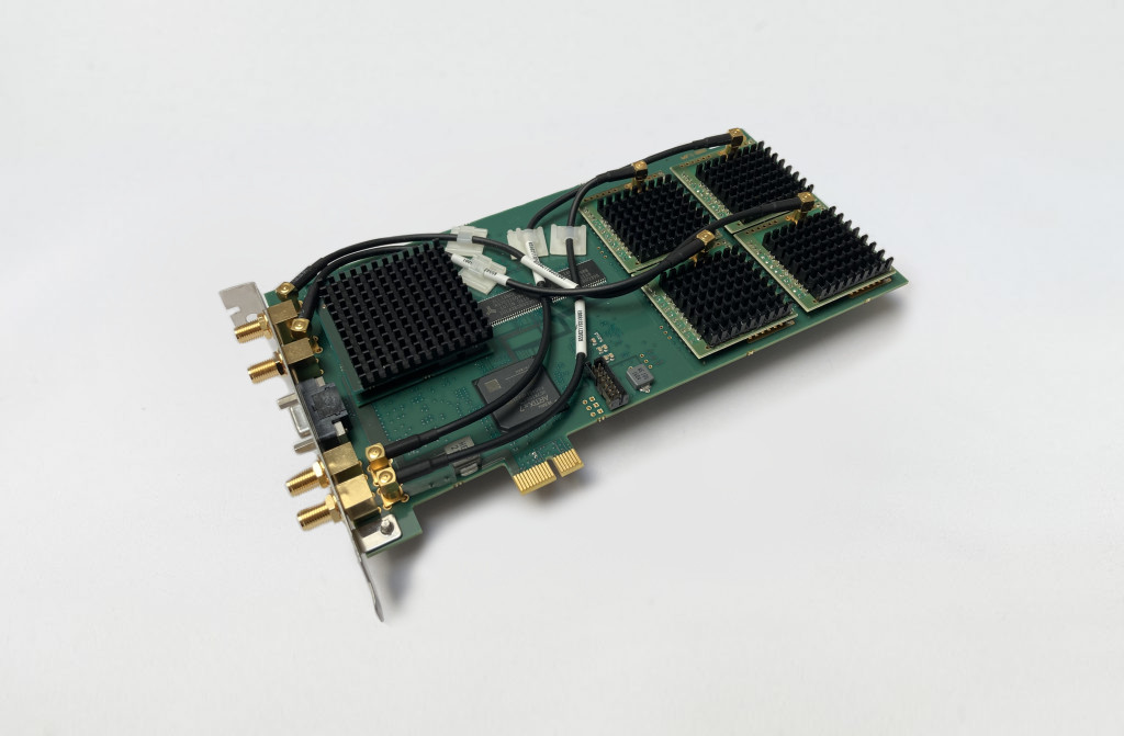
The SPC-QC-004 TCSPC module has three parallel TCSPC channels with a common reference channel on a single PCI-express board. Alternatively, the module can be operated with four absolute photon timing channels. The module features high temporal and spatial resolution, high peak count rate, and extraordinarily high timing stability. The SPC-QC-004 offers the usual modes for recording temporal waveforms of optical signals, sequential recording multi-wavelength recording, time- and parameter-tag recording, triggered accumulation of fast time series of curves and simultaneous fluorescence and phosphorecence decay recording.
Measurement Software Included
The SPCM operating and measurement software is included with all SPC series modules. SPCM provides online calculation and display (2D, 3D) of data (decay curves, FCS and FCCS) acquired in multiple operation modes. SPCM software undergoes active continuous development. SPCM receives frequent updates with new features and bug fixes. Read more…
FLIM and FCS Data Analysis
For advanced fluorescence lifetime single-curve data analysis, please use SPCImage.
For advanced visualisation and analysis of dynamic effects, please use SPCDynamics.
For advanced fluorescence correlation spectroscopy (FCS) and cross-correlation (FCCS) data analysis, please use Burst Analyzer.
Custom Programming Libraries (DLL, LabVIEW)
For automation and custom software integration, DLLs and LabVIEW drivers are available. Read more…
Specifications
|
Photon Channel |
|
|
Principle |
Constant Fraction Discriminator (CFD) |
|
Discriminator Input Bandwidth |
4 GHz |
|
Optimum Input Voltage Range |
-30 mV to -500 mV |
|
Min. Input Pulse Width |
200 ps |
|
Threshold |
0 to -500 mV |
|
Zero Cross Adjust |
-100 mV to 100 mV |
|
Syncronisation Channel |
|
|
Principle |
Constant Fraction Discriminator (CFD) |
|
Discriminator Input Bandwidth |
4 GHz |
|
Optimum Input Voltage Range |
-30 mV to -500 mV |
|
Min. Input Pulse Width |
200 ps |
|
Threshold |
0 to -500 mV |
|
Zero Cross Adjust |
-100 mV to 100 mV |
|
Frequency Range |
0 to 150 MHz |
|
Frequency Divider |
1 – 2 - 4 |
|
Adjustable Delay |
± 128 ns |
|
Time-Measurement Circuitry |
|
|
Principle |
Time-to-Digital Converter |
|
IRF Width, FWHM |
< 39 ps |
|
Typical RMS Timing Jitter |
16 ps |
|
Time Range, at 4096 Time Channels |
16 ns to 72 µs |
|
Min. Time / Channel |
4 ps |
|
Timing Stability, Range 16 ns, over 10 min |
< 5 ps RMS |
|
Diff. Nonlinearity |
< 1 % RMS |
|
Dead Time |
8 ns |
|
Histogram Modes |
|
|
Method |
on-board multi-dimensional histogramming process |
|
Peak Count Rate, Each Channel |
120 MHz |
|
Saturated Count Rate, Continuous |
40 MHz |
|
Max. Counts / Time Channel (Counting Depth) |
216 - 1 |
|
Max. No. Of Time Channels |
65,536 |
|
Overflow Control |
none, stop, repeat and correct |
|
Collection Time |
0.1 µs to 100,000 s |
|
Display Interval Time |
10 ms to 100,000 s |
|
Repeat Time |
0.1 µs to 100,000 s |
|
Synchronisation with Scanning (Scan Sync IN Mode |
Pixel, line and frame clocks from scanning device |
|
Routing |
4 bit, TTL |
|
Count Enable |
1 bit, TTL |
|
Experiment Trigger |
TTL |
|
Data Acquisition |
FIFO / Parameter-Tag Mode |
|
Method |
Parameter-tagging of individual photons, continuous writing to disk |
|
Online Display |
Decay functions, FCS, Cross-FCS, PCH MCS Traces |
|
FCS Calculation |
Multi-tau algorithm, online calculation and online fit |
|
Number of Counts of Decay/ Waveform Recording |
unlimited |
|
Peak Count Rate |
120 MHz |
|
Sustained Count Rate (Bus-Transfer Limit) |
40 MHz (Software dependent) |
|
Max. Counts / Time Channel (Counting Depth) |
unlimited |
|
Max. No. of Time Channels |
4096 |
|
On-board FIFO Buffer Capacity (Photons, per Channel) |
1.750,000 |
|
Macro Timer Resolution, Internal Clock |
2 ns, overflows marked by MOTF entry in data stream |
|
Routing |
4 bit, TTL/CMOS |
|
External Event Marker |
4 bit, TTL/CMOS |
|
Experiment Trigger |
TTL/CMOS |
|
Input Experiment Trigger |
TTL |
|
Operation Environment |
|
|
Operating System |
Windows 10, Windows 11 |
|
Bus Connector (Slot Type) |
PCIe |
|
Total Power Consumption |
approx. 12 W from +12 V |
|
Dimensions |
205 mm x 120 mm x 18 mm |
Downloads
Documents
Gallery