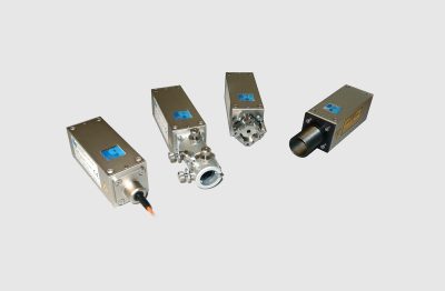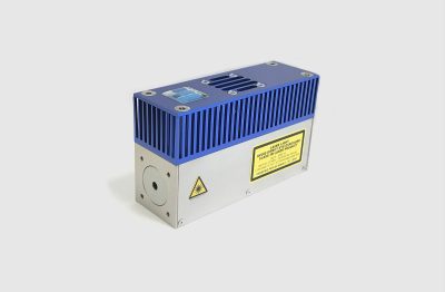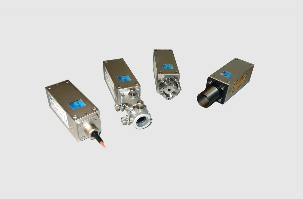
- Multi-Mode Picosecond Diode Lasers
- Free Beam or Multi-Mode Fiber Output
- Optical Power up to 60 mW
- Pulse Width Down to 65 ps
- Repetition Rate 20 MHz and 50 MHz
- External Trigger via Synchronisation Input
- Internal Power Stabilization Loop
- Fast ON / OFF / Multiplexing Capability
- All Electronics Integrated in 40 x 40 x 120 mm Case
- No External Driver Unit Required
- Simple +12 V Supply
- Size 40 x 40 x 120 mm3, with Cooling Fan 40 x 70 x 120 mm3
Description
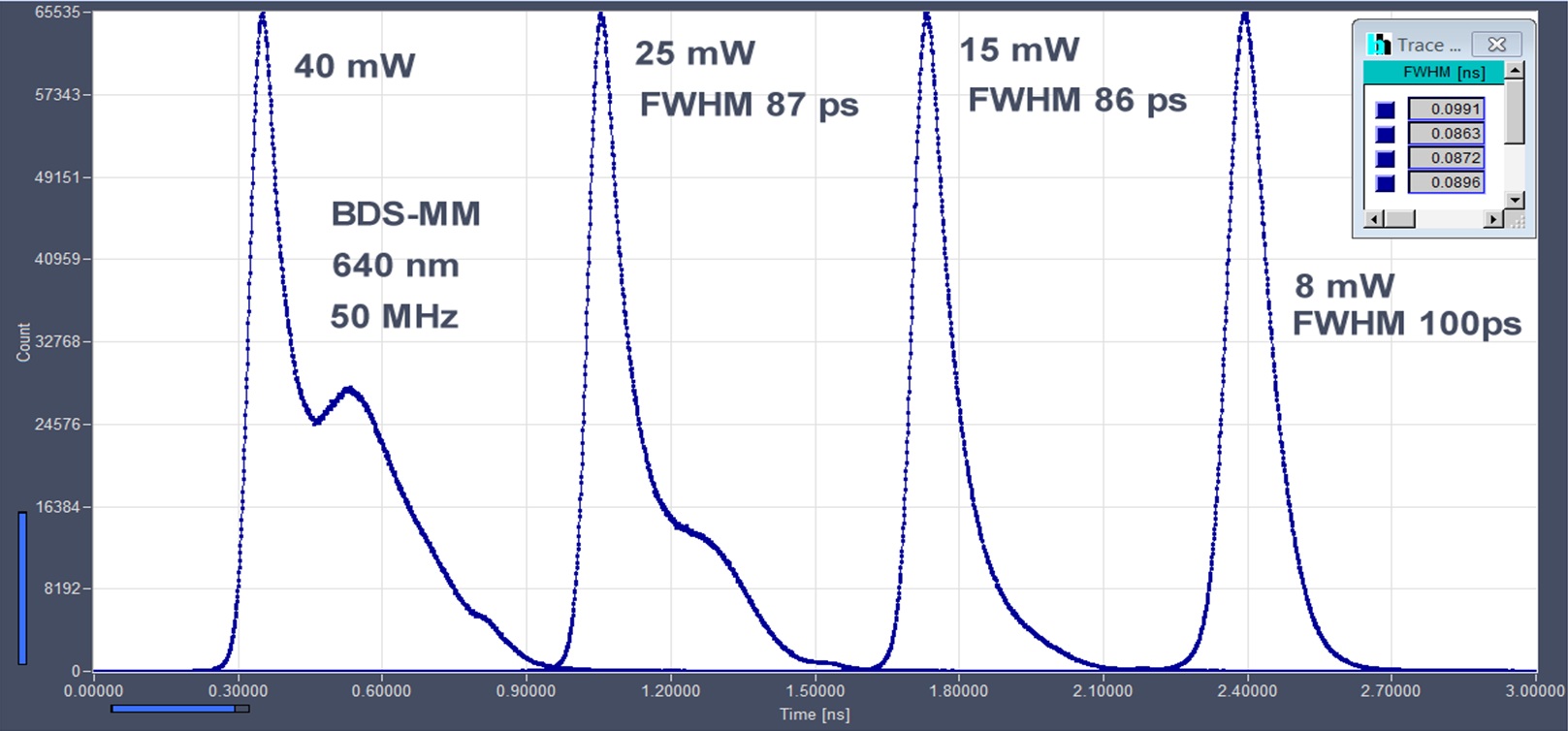
The BDS-MM devices are picosecond diode multimode lasers. Compared with the BDS-SM versions, the output power is considerably higher. The pulse shape remains near Gaussian up to about 15 mW at 50 MHz repetition rate, see figure below. However, the output beam is multi-mode and thus cannot be focused into a diffraction-limited spot. Maximum power is between 40 mW and 60 mW, depending on the wavelength version.
All the pulse driver and control circuitry is contained in the 40 x 40 x 120 mm laser head. All that is needed to operate the lasers is a +12 V power supply and a few control signals for setting repetition rate and optical power.
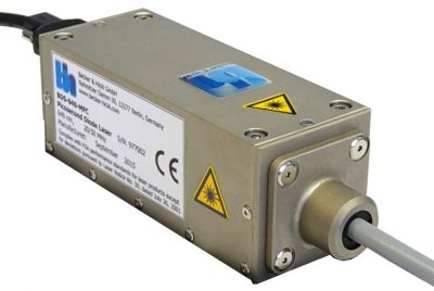
In OEM applications the laser head can be embedded as it is, with the the extarnal system providing the control signals. For stand-alone applications the LSB-C laser switch box or the LSB-C2 dual-laser switch boxes are available, see photos below. Software-generated control signals can be provides by the bh DCC-100 and DCU-400/800 detector/laser controllers.
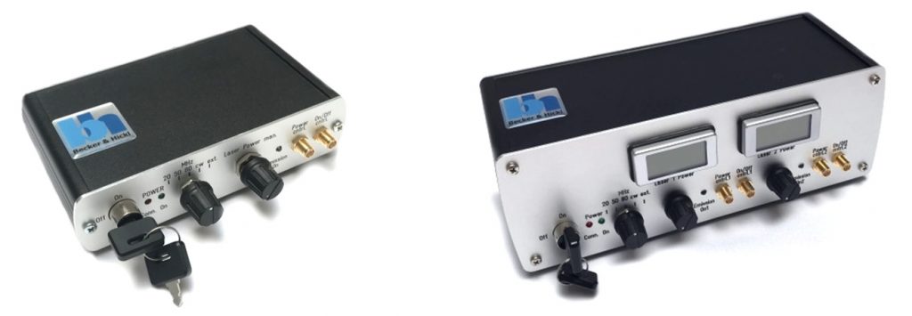
Due to an internal power regulation loop, the BDS-MM lasers feature extraodinarily stable optical power. Intensity drift by temperature changes and intensity noise by mode fluctuations in the laser diode are almost entirely suppressed. The lasers have a fast on/off function which can be used for beam blanking in scanning applications and for laser multiplexing. The reaction time of the optical output power to the ON/OFF control is on the order of a few microseconds.
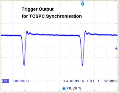
The BDS-MM lasers deliver a trigger output signal for synchronisation to bh TCSPC devices, see figure below. The output amplitude is sufficient for distribution of the trigger signal to several TCSPC modules. The timing stability of the trigger pulses versus the optical pulses is better than 5 ps. Extended warm-up times are not needed. After switch-on of the power supply, the timing is stable after less than a minute warm up time. The BDS-SM lasers can also be triggered externally. However, the trigger frequency should be in the range from 10 to 50 MHz in order to keep the intensity-regulation loop in the active range.
All BDS-MM lasers are multi-mode lasers. Multimode lasers deliver high optical power but the emission does not come from a single spot. That means the laser beam cannot be focused in a diffraction-limited spot or coupled into a single-mode fibre. If fibre coupling is desired multimode fibres of larger than 100 micrometers diameter must be used. Typical applications are NIRS and fNIRS experiments and fluorescence-lifetime spectrometers.
Specifications
|
|
BDS-MM |
|
Optical |
|
|
Wavelength / nm |
405, 450, 525, 640, 685, 785, 915, Others on Request |
|
Repetition Rate, Switchable by TTL Signal |
20 MHz and 50 MHz, Other Combinations on Request |
|
Pulse Width (FWHM, at Medium Power, at Maximum Power) |
65 - 120 ps, 120 - 300 ps |
|
Max. Optical Power |
10 mW to 60 mW at 50 MHz (Depends on Wavelength Version) |
|
Coupling Efficiency into Fibers (Multi-Mode, typ.) |
100 µm: 60 %, 200 µm: 80 %, 500 µm: 90 % |
|
Warm-up Time for Power and Pulse Shape Stabilisation after Power On |
1 min1) |
|
Trigger Output |
|
|
Pulse Amplitude |
-1 V (Peak) into 50 Ω |
|
Pulse Width |
1 ns |
|
Output Impedance |
50 Ω |
|
Connector |
SMA |
|
Jitter between Trigger and Optical Pulse |
< 10 ps |
|
Synchronisation Input |
|
|
Input Amplitude |
+3.3 V to +5 V into 50 Ω |
|
Duty Cycle |
10 to 30 %; DC Equivalent must be < 2.5 V |
|
Input Frequency |
20 to 60 MHz |
|
Switching from Internal Clock to Sync Input |
Automatic, by Average Voltage at Trigger Connector |
|
Control Inputs |
|
|
Frequency (20, 50 MHz) |
TTL / CMOS high |
|
Laser ON / OFF |
TTL / CMOS low |
|
Response of Optical Output to ON/OFF Signal |
< 4 µs for Power 10 to 100 % |
|
External Power Control |
Analog Input, 0 to +10 V |
|
Response Time of Optical Output to Power Control |
< 4 µs for Power 10 to 100 % |
|
Power Supply |
|
|
Power Supply Voltage |
+9 V to +15 V |
|
Power Supply Current at 12 V |
200 mA to 500 mA 2) |
|
Mechanical Data |
|
|
Dimensions (OEM) |
40 mm x 40 mm x 120 mm |
|
Dimensions (w/ Cooling) |
40 mm x 70 mm x 120 mm |
|
Mounting Thread |
four M3 Holes |
|
Heat Sink Requirements |
< 2 °C / W 3) |
|
Maximum Values |
|
|
Power Supply Voltage |
0 V to +15 V |
|
Voltage at 'Laser ON/OFF' and 'Frequency' Inputs |
-2 V to +7 V |
|
Voltage at 'Laser Power' Input |
-12 V to +12 V |
|
Ambient Temperature |
15 °C to +35 °C 3) |
(1) Operation below 15 °C ambient temperature may result in extended warm-up time.
(2) Depends on case temperature due to laser diode cooling. Cooling current changes with case temperature.
(3) OEM version without active cooling must be mounted on heat sink. Case temperature must remain below 40 °C.

